Nad 310 amplifier - blowing fuse in plug

Page 2 - Seeking answers? Join the What HiFi community: the world's leading independent guide to buying and owning hi-fi and home entertainment products.
A

Anonymous

Guest
stevieg330 said:
Hi Andrew,

is the damage just in that area or has the whole wire got hot? Bit hard to tell from the photo.

Cheers

Steve

Looks like just in that area - no damage to the black wire it was nestling underneath, and the rest of the red wire and the other three secondary wires look to be all okay (well, I can't see any heat damage or melting on the sheathing!).

Cut the wire where it was burned out and trimmed it back and it looks okay - it's a single strand of copper wire (for some reason I was expecting it to be multiple strand....)

Will try to *** out later to pick up some more 3A fuses and some solder (have run out) and then dig out the soldering iron tonight if I get the time. Let's get this baby back up and working! :)
 

Mooly

New member
Jun 10, 2011
1
0
0
Visit site
That looks promising...

A good tip for safely powering up amps and so on is to replace the mains fuse with a 100 watt filament bulb (usual warnings about doing it safely with nothing anyone can touch). That limits current and even a dead short would just light the bulb.
 
A

Anonymous

Guest
Mooly said:
That looks promising...

A good tip for safely powering up amps and so on is to replace the mains fuse with a 100 watt filament bulb (usual warnings about doing it safely with nothing anyone can touch). That limits current and even a dead short would just light the bulb.

Never heard that one before - care to elaborate or linky to how I do this? :) Thanks!
 

Mooly

New member
Jun 10, 2011
1
0
0
Visit site
The bulb goes in series with the mains to the amp.

Where in the circuit from a technical point is irrelevant as the primary side is a series circuit. The electrical path is normally from Live>Plug fuse>Live lead>Fuse in amp>Switch>transformer>neutral back to plug.

You just interrupt the circuit wherever is most convenient and place an ordinary 60 or 100 watt bulb across the "break". The resistance of the filament is low when cold and so allows a modest current to flow which is normally enough to power a class b or ab amp in its quiescent state. It's a technique normally used when repairing output stages and ensure output transistors survive fault conditions allowing the amp to be worked on. If there were a short or problem causing excess current the bulb would light and the voltage rails in the amp collapse preventing damage.

As this is a general forum, safety can not be stressed to highly. You have to make sure that anything you rig up is insulated and out of reach of being touched.
 
A

Anonymous

Guest
Quick update - trimmed and resoldered the burnt out wire last night, but still no joy. It's popping 3A fuses like they'r going out of fashion ;-)

Didn't have the necessary kit for the 100W bulb current limiter, but will try to pick up a lamp holder etc at the weekend.

Is there any way to test the toroid to see if it's working correctly? Seeing as it keeps blowing fuses, I can't see how to test the output.

If it needs a replacement, one company came back to me with this toroidal transformer from their standard range: http://www.airlinktransformers.com/chassis_mounting_toroidal_transformers_standard_range/3-CM0050240.html The only note to add to that product was the following included in the email: "If you require a split primary (115v+115v) that would be a custom built unit at £35 plus vat and delivery". Can anyone advise if split primary is necessary (not sure what that actually means) and how it would differ from the additional split primary option on the product page (trying to reconcile the difference in price...)?

Thanks again!
 

Mooly

New member
Jun 10, 2011
1
0
0
Visit site
I still find it hard to believe the tranny is duff...

Here is what I would do... and remember safety first.

A 100% conclusive test is to disconnect the secondary leads of the tranny in the amp and if it still blows the fuse when powered up, then yes, it is duff. Looking at the circuit you could just take out the two secondary fuses to achieve isolating the winding but lets be 100% sure and isolate it physically.

You could also to avoid destroying more fuses, get a 100 or 60 watt bulb and solder two wires to the bulb terminals. Fit an "old" 3 pin plug to the amp mains lead and remove the fuse in the plug. Now solder the two leads from the bulb across the fuseholder. The bulb now takes the place of the fuse. Again with the secondary disconnected power up. The bulb should emit a pulse of light as the transformer draws an initial surge current and then the bulb should all but go out. If the bulb stays lit then the tranny is duff.

Also it would be worth putting your meter on "diode check" and with the amp OFF and UNPLUGGED measure across C301 and C302 in turn to see if it reads 0.00 on the meter indicating a short circuit rectifier.

Edit... A split primary isn't needed for the UK. It allows multi voltage operation such as USA/Europe. You just want a 230Vac primary. If you get one with a split primary then they are connected in series for 230 volt operation. Lets make sure it is duff first. Did you look at the one from CPC I posted a link too. Would that physically fit ?
 
A

Anonymous

Guest
Mooly said:
I still find it hard to believe the tranny is duff...

Here is what I would do... and remember safety first.

A 100% conclusive test is to disconnect the secondary leads of the tranny in the amp and if it still blows the fuse when powered up, then yes, it is duff. Looking at the circuit you could just take out the two secondary fuses to achieve isolating the winding but lets be 100% sure and isolate it physically.

You could also to avoid destroying more fuses, get a 100 or 60 watt bulb and solder two wires to the bulb terminals. Fit an "old" 3 pin plug to the amp mains lead and remove the fuse in the plug. Now solder the two leads from the bulb across the fuseholder. The bulb now takes the place of the fuse. Again with the secondary disconnected power up. The bulb should emit a pulse of light as the transformer draws an initial surge current and then the bulb should all but go out. If the bulb stays lit then the tranny is duff.

Also it would be worth putting your meter on "diode check" and with the amp OFF and UNPLUGGED measure across C301 and C302 in turn to see if it reads 0.00 on the meter indicating a short circuit rectifier.

Edit... A split primary isn't needed for the UK. It allows multi voltage operation such as USA/Europe. You just want a 230Vac primary. If you get one with a split primary then they are connected in series for 230 volt operation. Lets make sure it is duff first. Did you look at the one from CPC I posted a link too. Would that physically fit ?

Right - noted about disconnecting secondaries entirely - will give this a try this evening/tomorrow :)

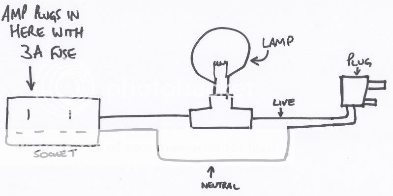
Re the dim bulb tester, I can probably pick up a cheap lamp holder when I'm out tomorrow, and I reckon that I have an extension lead kicking around spare somewhere, so if I connect the lamp in series across the live wire in the extension lead and then plug the amp (with 3A fuse fitted) into that, will that work? I did a little drawing to explain what I mean:

DimBulbTester_0001.jpg


Thanks for the CPC link - that's going to be a touch too big. The transformer from Airlink Transformers would fit thoug (a bit smaller actually). Do the specs of that one match up okay?
 

stevieg330

New member
May 6, 2005
3
0
0
Visit site
Hi Andrew and Mooly,

Sorry for the delay in replying, been working for a living!

I think the only thing left to do is remove the secondarys from the PSU board and see what happens, as one of the first tests we did was to remove the fuses and it still blew the plug fuse. From the circuit diagram, removing the fuses opens one side of the connection to the rectifiers.

Cheers

Steve
 
A

Anonymous

Guest
Mooly said:
Also it would be worth putting your meter on "diode check" and with the amp OFF and UNPLUGGED measure across C301 and C302 in turn to see if it reads 0.00 on the meter indicating a short circuit rectifier.

Never done a diode check before, but always willing to learn something new. To be clear, am I measuring across the +ve and -ve posts on each capacitor (I can access these on the underside of the PCB)? What kind of reading should I be looking for - for reference, in diode check mode, my Velleman multimeter has a 1 on the display (ie before testing anything, without the probes connected to anything) :)

Many thanks in advance for your help (again)
 

Mooly

New member
Jun 10, 2011
1
0
0
Visit site
You've got it for the bulb tester :)

The "diode check" range on the meter works as follows. The meter passes a very small current through the device under test and on diode range it is actually showing the voltage "dropped" across whatever the probes are connected to.

Now reading parts in circuit does give misleading results but if a part is short circuit it will show up of course and the meter would read essentially 0.00 meaning "no volts" present between the probes. So that is worth checking.

The tranny in your link could be too high on voltage. It's quoted as 40 volt with a 14% regulation. That gives around 45.6 volts with no or light loading. That translates to 64 volts DC when rectified and smoothed which is over the working voltage of the caps in the amp.

One step at a time though... lets prove the tranny good or not first.
 

TRENDING THREADS

Latest posts