Hello to all friends of the vinyl record
I am in the process of finishing my prototype of a stereo record-cutting device.
Since I still have some flexibility in operation and design, I wanted to ask HiFi lovers how they imagine such a device.
In this context I would like to introduce myself: I am a development engineer from Austria, 55 years old, love analog HiFi technology and records. I have been working on the development of the record cutter for private users for many years and am close to completion.
To meet the user needs as good as possible I have prepared a short questionnaire. If you are interested in playing records and possibly also in a cutting device in principle, I ask you to fill out the questionnaire at the end of the article (anonymously, of course). If you are not interested, then perhaps the following information will inspire you.
In any case, thank you for the interest and especially if you fill out the questionnaire.
But before that I would like to publish a post with background basic knowledge about record cutting.
GENERAL INFORMATION ABOUT RECORD CUTTERS
HISTORY:
Briefly summarized, the cutting of grooves in records began in 1887 which (after appropriate processing) could be played on a gramophone. Shellac records came on the market from 1896 and these were gradually replaced by vinyl records from 1930.
(See also https://de.wikipedia.org/wiki/Schallplatte )
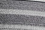
Record grooves (Wikipedia)
TODAY VINYL PLATE MANUFACTURE (simple explanation):
Even today, record blanks are made on cutting machines from the 1980s. In this process, the master signal (tape or digital) is cut into a record blank via a cutting head. The record blank consists of a metal plate covered with a special lacquer layer. The lacquer layer is relatively soft and therefore easy to cut with almost no background noise. The blank is moved on a powerful and smooth-running turntable. The cutting head consists of two (stereo) speakers arranged at 90° and moving a sapphire stylus. The graver cuts the signal into the record. The contact force, position and cutting angle are precisely maintained. As with a lathe, the cutting head is moved from the outside to the inside. This movement can be constant or variable (quiet sound sources = little feed; loud places = large feed).
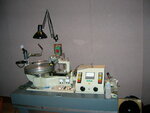
Neumann record cutter (Wikipedia).
Only one side is cut at a time. The two cut plates (side A and B) are then sent to the pressing plant. There the lacquer plates are galvanically metal coated to get one negative (father) each. From this, several positives (mothers) are again galvanically produced, from each of which several negatives (sons) are then produced. These sons are then clamped in the press and the vinyl granulate (PVC/PVA) is pressed into records at high pressure and temperature. Theoretically, the records could already be pressed from the "father", but the press mold deteriorates with each pressing and can only be used 400x.
With DMM cuts are not cut into lacquer, but into a copper plate (Direct Metal Mastering). This is more difficult for the cutting head, but it eliminates the processing step of electroplating for "father & mother".
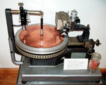
Record cutter DMM (Wikipedia)
(See also http://mikiwiki.org/wiki/Schallplattenherstellung and https://www.fairaudio.de/hintergrun...railroad-tracks-masteringstudio-besuch-1-dwt/ ).
A problem for the panel industry arose in February 2020 when the Apollo/Transco plant in California burned down. Nearly 85% of the world's paint blank panels were made there, and there are still no new manufacturers.
(See also https://en.wikipedia.org/wiki/Apollo_Masters_Corporation_fire )
MANUFACTURING SMALL SERIES (simple explanation):
For small series (about 1-100 pieces), cutting is done into the record blank in real time (sides A and B) and the cut record can be played directly on the turntable. Lacquer-coated records are not suitable for this, they are much too expensive (approx. $ 80 per piece per side) and too soft. The needle of the turntable would destroy the record after 2-3x playing and also the playback needle is destroyed by sticking (lacquer). Therefore, we cut on PVC or PETG plastic. The advantages are the cost (about $ 6 - $ 10 each) and the durability like vinyl records. The disadvantage is that it is much more complex and difficult to cut and instead of sapphires a diamond stylus is necessary. Also, the silent spots are a bit louder than with pressed records.
DID YOU KNOW THAT A RECORD CUTTER HAS THE FOLLOWING COMPONENTS OR FEATURES?
THE TURNTABLE PLATEN:
It must be strong in drive, have a stable bearing, have high synchronization characteristics, and be precision manufactured. In addition, it must be appropriately manufactured to prevent "slippage" between the plate and platen. Ideally, speeds of 33.3; 45; 78 rpm and also 16.7; 22.5; 39 rpm for "half speed mastering" can be performed. Plate sizes 7", 10" and 12" (30cm) should be possible. Ideally also 14" plates. The larger the record holder the more precise and stable the platter must be built.
THE CUTTING HEAD:
Regardless of whether it is a mono or stereo head, the cutting head should be able to transmit frequency ranges from 20Hz to 18kHz at best. At the same time, the resonance frequencies should be as low as possible. Stereo heads should also provide good channel separation.
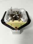
Cutting head Neumann (Wikipedia)
THE CUTTING CONCEPT:
Basically, a distinction is made between pressing (embedding) and cutting (cutting).
In embedding, the stylus (tungsten, sapphire, or diamond needle) is pressed into the surface by moving the angle of the stylus in the direction of travel, i.e., pulling (similar to drawing a pattern in butter with a fork). The contact pressure must be higher, and the quality is somewhat lower (limited high frequencies). Also, the stereo effect is almost non-existent. However, there is no "cutting thread".
When cutting, the graver is at 90° or even against the running direction (similar to linocut). This creates a "cutting thread" from the material that has been removed. This thread must be sucked off, otherwise it gets caught or comes between the graver and the plate and can cause the graver to jump. The quality is much higher (high frequencies are possible) and it is cut with sapphire or diamond needles.
THE CUTTING GRAVER:
The cutting stylus is made of sapphire or diamond. Unlike pickup systems, the flanks (straight) are at a 90° angle and the tip is not rounded. (The pickup - whether round or oval cut - scans the flanks when played). Durability ranges from 10 plate sides (for sapphire lacquer cuts in the master area) to 100 plate sides (for diamond PETG cuts). Diamond stylus can be resharpened several times.
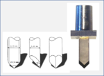
Cutting stylus
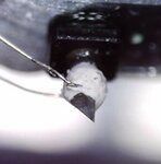
Cutting stylus with heating wire
THE PLATEN PRESSURE:
Similar to a record player, the graver must cut (press) into the plate with a certain bearing force. The contact pressure determines the cutting width (approx. 40µm) and depth (approx. 20µm). If no signal is transmitted (start groove, pause between two songs, end groove), the cutting depth decreases, which in turn must be compensated, otherwise the needle may "jump" during playback. The contact pressure can also compensate for a slightly worn stitch.
STYLUS HEATING:
This involves a heating wire wrapped around the cutting stylus with current flowing through it. A heated stylus can reduce ambient noise (silent cut).
PLATE HEATING:
Even more important than graver heating is plate heating. A "warm" plate is better and, above all, quieter to cut. The plate temperature for PETG plates should be between 30° and 40°. The temperature thus also influences the "cutting thread" of the cut material. Too high temperatures deform the blank and cause the "cutting thread" to melt and stick together during cutting (making suction impossible). Temperatures that are too low reduce the cutting quality.
THE GROOVE SPACING:
One groove per side! By groove spacing is meant the distance of the groove from one revolution to the next. Depending on the volume during recording and the frequency (basses need more space), in extreme cases the groove can deflect up to 200µm in each direction (signal width maximum 400µm)! So that the cut groove does not overlap with the groove on the following rotation, a "feed" of approx. 420µm must therefore be carried out (with embedding, the distance must be even greater, because some material is pressed into the groove of the previous groove when pressing).
With constant groove spacing (420µm), the time for music would soon run out (at 33.3rpm max. 6 minutes). If you cut quieter and cut less bass (e.g.: from 40Hz) you can cut 20 minutes of music.
With variable groove spacing, the "feed" changes depending on volume and basses. So for quiet parts it is reduced to 80µm and for loud parts it is increased to 400µm. Thus, one can record longer even with "loud" cuts. However, it is a very complex procedure because ideally the music signal must be available 1.8 seconds before the cut.
In any case, the feed must be absolutely uniform, because understandably a "jerky" inaccuracy of 1µm would already produce a well audible sound. High-precision drive spindles are used for this purpose.
WHITE NOISE:
"White noise is noise with a constant power density spectrum in a certain frequency range. White noise is perceived as a noise with a strong treble emphasis. White noise, which is limited in bandwidth, is commonly used in engineering and science to represent noise in an otherwise ideal model (see Wikipedia)."
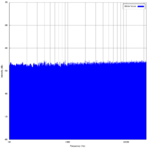
White Noise Frequency Analysis
This test signal forms "simultaneously" a tone in all frequencies (e.g.: 20Hz - 20kHz). Each frequency is transmitted with the same "dB intensity". For testing this signal is ideal, because at the end a "straight" signal curve should come out.
In the figure the groove spacing is constant with 300µm. Different volumes during cutting show the different "deflections" of the groove (the groove width itself is relatively constant at 48µm).

Cut white noise signal (different volume)
RECORD MASTERING:
This does not mean mastering a piece of music, which is basically used to improve the raw recording and prevent peaks (you can do that anyway). Rather, it refers to the preparation of a piece of music for a vinyl recording. Because unlike tape or digital recordings, here the groove is cut (or pressed) mechanically. Thus, the mechanical limitations of the technology must be considered:
IRIAA EQUALIZER:
If a piece of music were cut unfiltered, then low frequencies (20-400Hz) would be reproduced far too loudly and high frequencies (5kHz and above) would be almost inaudible. This is because 10W of a signal at 100Hz can move the speaker, and thus the cutting stylus, slowly and strongly. 10W of a signal at 5,000Hz moves the cutting stylus quickly but with hardly any noticeable excursion. (This has to do with the ratio of frequency to amplitude).
Therefore, the cutting characteristic IRIAA (Inverse RIAA Equalization Curve) was established in the 1960s.
This attenuates low frequencies and amplifies high frequencies. (Phono amplifiers are equipped with RIAA equalizers, which boosts low frequencies and attenuates high frequencies to the same degree when the record is played.
(See https://de.wikipedia.org/wiki/Schneidkennlinie )

RIAA and IRIAA characteristics
HIGH-PASS FILTER (LOWCUT):
A high-pass filter allows "high" frequencies to pass. Since in audio these filters are used to cut a frequency band below a range of e.g.: 20Hz (i.e., to let frequencies from 20Hz pass) they are also called LOWCUT filters. During plate cutting, frequencies that are too low should be avoided. Because they consume "a lot of space" or because in extreme cases the needle can jump out of the groove during playback.
A Low Cut-Filter can be digital or analog and should be variable adjustable for record cutting (e.g.: 20-30-40-60 Hz)

low cut filter (20Hz -12dB)
LOW-PASS FILTER (HIGHCUT):
A low-pass filter allows "low" frequencies to pass. Since in audio these filters are used to cut a frequency band above a range of e.g.: 20kHz (i.e., pass frequencies up to 20kHz) they are also called HIGH CUT filters. When cutting plates, too high frequencies should be avoided because the cutting head is extremely stressed (coils can burn out).
This is caused by the strong amplification of the IRIAA characteristic which is amplified by +20dB at 20kHz. On the 20W loudspeaker can be 300W (if the amplifier has the power). At 10kHz the amplification is "only" +13dB.
A High Cut filter can be digital or analog and should be variably adjustable for plate cutting (e.g.: 9kHz-12kHz-15kHz-18kHz-20kHz).

high cut filter (20kHz -12dB)
ELLIPTIC EQUALIZER (EEQ):
This equalizer is only needed for stereo cuts. Since it can happen with music pieces in the range of very low frequencies in stereo that the left and right channel play the bass out of phase, it would be cut in this way. The problem arises during playback, because then the needle jumps out of the groove. Therefore, it must be ensured already during cutting that such a thing does not happen. Therefore, the EEQ (I like to call it MONO-BASS-EQUALIZER) is used. It "monoizes" low frequencies, can be digital or analog and should be variably adjustable for plate cutting (e.g.: mono to 75hZ, to15Hz and to 300hZ). In addition, it should pass on undistorted stereo signals.
PARAMETRIC EQUALIZER:
Similar to a graphic equalizer, this boosts certain frequencies and cuts others. However, it does not do this with one control per frequency range. The Parametric EQ basically has three controls:
1A: FREQUENCY: This control selects continuously the frequency range (e.g.: 550Hz).
1B: GAIN: This control selects continuously the gain or attenuation of the frequency (e.g.: +4.5dB).
1C: Q: This control selects continuously the frequency bandwidth - i.e., how "sharp" or "flat" the frequency characteristic should be. For example, a Q=15 will only affect a range of 0.1 octaves (peaked) while a Q=0.5 will affect about 2.5 octaves (flat).
(See https://13db.de/wissen/q-und-bandbreite-am-eq/)

Parametric EQ (left with Q=0.5; right with Q=15)
But such a parametric equalizer usually does not consist of only one unit, but of several (4 to 6). With its extreme distortion characteristics can be created.
On the one hand, this serves to compensate the resonance curves of the cutterhead, but also to master your own music cuts. You can thus cut with more bass, mid or treble.

Signal distortion through four parametric EQ
FEEDBACK COIL EQUALIZER:
Modern cutting heads have small feedback coils (one per channel). The movement of the speakers (which are fed by the signal) is measured via the feedback coils. Then the "original" music signal and the feedback coil signal are compared, compensating for resonances. This means a "clean" resonance compensated cutting.
LIMITER:
A limiter, or limiter, is a dynamics-processing effects device in a rig or plug-in that turns down the output level (amplitude of the voltage of the audio signal) to a specific value. This is set by the "limiter threshold" (threshold value). This prevents overdriving (clipping) during cutting.
AMPLIFIER - POWER AMPLIFIER:
The more qualitative the amplifier, the more qualitative the cut. The special thing about an amplifier for record cutting is that it needs high power, and this high power is available quickly (without time delay). Although the speakers in the cutterhead have only 10W, 20W or 40W speaker coils, the power amplifier needs about 300W.
If a loudspeaker e.g.: 15W reproduces its power at 1kHz, it also needs twice the power at double the frequency. So, at 2kHz about 30W; at 4kHz about 60W; at 8kHz about 120W and at 16kHz about 240W! Consequently, for 20kHz about 300W is needed.
Of course, 300W is a very high load for a 15W loudspeaker, even if it occurs only for a very short time, which heats up the loudspeaker considerably. The Neumann cutting equipment in the 80's had helium cooling of the loudspeakers for this purpose, in order to be able to cut up to 20kHz (and were at their limits). Modern tweeters are ferrofluid cooled and therefore have a higher power handling. Nevertheless, they usually "only" cut up to 16kHz or 18kHz.
THE SUCTION:
The aforementioned "cutting filament" that results from the removed material must be extracted via a suction tube (then a hose) directly next to the cutting stylus. In the best case, this is implemented by a high-performance rotary pump.
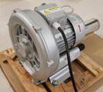
Rotary pump
Piston pumps would create a pulsating air flow, which in turn (because of its proximity to the cutting graver) would cause the graver to move back and forth, which in turn would be audible during playback. A heavy-duty rotary pump produces a steady flow of air and does not overheat. The "cutting thread" must still be caught and collected in a container before the pump, as it would damage the pump in the long run.
I hope this rough overview could present understandably the basis of record cutting.
Now I ask you to fill out the questionnaire (anonymously), so that I can better understand needs and expectations of HiFi lovers - regardless of whether you would ever buy such a device or not.
The questionnaire is created on Google Forms, includes about 20 questions, and takes about five minutes to complete.
In any case, thank you for your interest
Thomas
I am in the process of finishing my prototype of a stereo record-cutting device.
Since I still have some flexibility in operation and design, I wanted to ask HiFi lovers how they imagine such a device.
In this context I would like to introduce myself: I am a development engineer from Austria, 55 years old, love analog HiFi technology and records. I have been working on the development of the record cutter for private users for many years and am close to completion.
To meet the user needs as good as possible I have prepared a short questionnaire. If you are interested in playing records and possibly also in a cutting device in principle, I ask you to fill out the questionnaire at the end of the article (anonymously, of course). If you are not interested, then perhaps the following information will inspire you.
In any case, thank you for the interest and especially if you fill out the questionnaire.
But before that I would like to publish a post with background basic knowledge about record cutting.
GENERAL INFORMATION ABOUT RECORD CUTTERS
HISTORY:
Briefly summarized, the cutting of grooves in records began in 1887 which (after appropriate processing) could be played on a gramophone. Shellac records came on the market from 1896 and these were gradually replaced by vinyl records from 1930.
(See also https://de.wikipedia.org/wiki/Schallplatte )

Record grooves (Wikipedia)
TODAY VINYL PLATE MANUFACTURE (simple explanation):
Even today, record blanks are made on cutting machines from the 1980s. In this process, the master signal (tape or digital) is cut into a record blank via a cutting head. The record blank consists of a metal plate covered with a special lacquer layer. The lacquer layer is relatively soft and therefore easy to cut with almost no background noise. The blank is moved on a powerful and smooth-running turntable. The cutting head consists of two (stereo) speakers arranged at 90° and moving a sapphire stylus. The graver cuts the signal into the record. The contact force, position and cutting angle are precisely maintained. As with a lathe, the cutting head is moved from the outside to the inside. This movement can be constant or variable (quiet sound sources = little feed; loud places = large feed).

Neumann record cutter (Wikipedia).
Only one side is cut at a time. The two cut plates (side A and B) are then sent to the pressing plant. There the lacquer plates are galvanically metal coated to get one negative (father) each. From this, several positives (mothers) are again galvanically produced, from each of which several negatives (sons) are then produced. These sons are then clamped in the press and the vinyl granulate (PVC/PVA) is pressed into records at high pressure and temperature. Theoretically, the records could already be pressed from the "father", but the press mold deteriorates with each pressing and can only be used 400x.
With DMM cuts are not cut into lacquer, but into a copper plate (Direct Metal Mastering). This is more difficult for the cutting head, but it eliminates the processing step of electroplating for "father & mother".

Record cutter DMM (Wikipedia)
(See also http://mikiwiki.org/wiki/Schallplattenherstellung and https://www.fairaudio.de/hintergrun...railroad-tracks-masteringstudio-besuch-1-dwt/ ).
A problem for the panel industry arose in February 2020 when the Apollo/Transco plant in California burned down. Nearly 85% of the world's paint blank panels were made there, and there are still no new manufacturers.
(See also https://en.wikipedia.org/wiki/Apollo_Masters_Corporation_fire )
MANUFACTURING SMALL SERIES (simple explanation):
For small series (about 1-100 pieces), cutting is done into the record blank in real time (sides A and B) and the cut record can be played directly on the turntable. Lacquer-coated records are not suitable for this, they are much too expensive (approx. $ 80 per piece per side) and too soft. The needle of the turntable would destroy the record after 2-3x playing and also the playback needle is destroyed by sticking (lacquer). Therefore, we cut on PVC or PETG plastic. The advantages are the cost (about $ 6 - $ 10 each) and the durability like vinyl records. The disadvantage is that it is much more complex and difficult to cut and instead of sapphires a diamond stylus is necessary. Also, the silent spots are a bit louder than with pressed records.
DID YOU KNOW THAT A RECORD CUTTER HAS THE FOLLOWING COMPONENTS OR FEATURES?
THE TURNTABLE PLATEN:
It must be strong in drive, have a stable bearing, have high synchronization characteristics, and be precision manufactured. In addition, it must be appropriately manufactured to prevent "slippage" between the plate and platen. Ideally, speeds of 33.3; 45; 78 rpm and also 16.7; 22.5; 39 rpm for "half speed mastering" can be performed. Plate sizes 7", 10" and 12" (30cm) should be possible. Ideally also 14" plates. The larger the record holder the more precise and stable the platter must be built.
THE CUTTING HEAD:
Regardless of whether it is a mono or stereo head, the cutting head should be able to transmit frequency ranges from 20Hz to 18kHz at best. At the same time, the resonance frequencies should be as low as possible. Stereo heads should also provide good channel separation.

Cutting head Neumann (Wikipedia)
THE CUTTING CONCEPT:
Basically, a distinction is made between pressing (embedding) and cutting (cutting).
In embedding, the stylus (tungsten, sapphire, or diamond needle) is pressed into the surface by moving the angle of the stylus in the direction of travel, i.e., pulling (similar to drawing a pattern in butter with a fork). The contact pressure must be higher, and the quality is somewhat lower (limited high frequencies). Also, the stereo effect is almost non-existent. However, there is no "cutting thread".
When cutting, the graver is at 90° or even against the running direction (similar to linocut). This creates a "cutting thread" from the material that has been removed. This thread must be sucked off, otherwise it gets caught or comes between the graver and the plate and can cause the graver to jump. The quality is much higher (high frequencies are possible) and it is cut with sapphire or diamond needles.
THE CUTTING GRAVER:
The cutting stylus is made of sapphire or diamond. Unlike pickup systems, the flanks (straight) are at a 90° angle and the tip is not rounded. (The pickup - whether round or oval cut - scans the flanks when played). Durability ranges from 10 plate sides (for sapphire lacquer cuts in the master area) to 100 plate sides (for diamond PETG cuts). Diamond stylus can be resharpened several times.

Cutting stylus

Cutting stylus with heating wire
THE PLATEN PRESSURE:
Similar to a record player, the graver must cut (press) into the plate with a certain bearing force. The contact pressure determines the cutting width (approx. 40µm) and depth (approx. 20µm). If no signal is transmitted (start groove, pause between two songs, end groove), the cutting depth decreases, which in turn must be compensated, otherwise the needle may "jump" during playback. The contact pressure can also compensate for a slightly worn stitch.
STYLUS HEATING:
This involves a heating wire wrapped around the cutting stylus with current flowing through it. A heated stylus can reduce ambient noise (silent cut).
PLATE HEATING:
Even more important than graver heating is plate heating. A "warm" plate is better and, above all, quieter to cut. The plate temperature for PETG plates should be between 30° and 40°. The temperature thus also influences the "cutting thread" of the cut material. Too high temperatures deform the blank and cause the "cutting thread" to melt and stick together during cutting (making suction impossible). Temperatures that are too low reduce the cutting quality.
THE GROOVE SPACING:
One groove per side! By groove spacing is meant the distance of the groove from one revolution to the next. Depending on the volume during recording and the frequency (basses need more space), in extreme cases the groove can deflect up to 200µm in each direction (signal width maximum 400µm)! So that the cut groove does not overlap with the groove on the following rotation, a "feed" of approx. 420µm must therefore be carried out (with embedding, the distance must be even greater, because some material is pressed into the groove of the previous groove when pressing).
With constant groove spacing (420µm), the time for music would soon run out (at 33.3rpm max. 6 minutes). If you cut quieter and cut less bass (e.g.: from 40Hz) you can cut 20 minutes of music.
With variable groove spacing, the "feed" changes depending on volume and basses. So for quiet parts it is reduced to 80µm and for loud parts it is increased to 400µm. Thus, one can record longer even with "loud" cuts. However, it is a very complex procedure because ideally the music signal must be available 1.8 seconds before the cut.
In any case, the feed must be absolutely uniform, because understandably a "jerky" inaccuracy of 1µm would already produce a well audible sound. High-precision drive spindles are used for this purpose.
WHITE NOISE:
"White noise is noise with a constant power density spectrum in a certain frequency range. White noise is perceived as a noise with a strong treble emphasis. White noise, which is limited in bandwidth, is commonly used in engineering and science to represent noise in an otherwise ideal model (see Wikipedia)."

White Noise Frequency Analysis
This test signal forms "simultaneously" a tone in all frequencies (e.g.: 20Hz - 20kHz). Each frequency is transmitted with the same "dB intensity". For testing this signal is ideal, because at the end a "straight" signal curve should come out.
In the figure the groove spacing is constant with 300µm. Different volumes during cutting show the different "deflections" of the groove (the groove width itself is relatively constant at 48µm).

Cut white noise signal (different volume)
RECORD MASTERING:
This does not mean mastering a piece of music, which is basically used to improve the raw recording and prevent peaks (you can do that anyway). Rather, it refers to the preparation of a piece of music for a vinyl recording. Because unlike tape or digital recordings, here the groove is cut (or pressed) mechanically. Thus, the mechanical limitations of the technology must be considered:
IRIAA EQUALIZER:
If a piece of music were cut unfiltered, then low frequencies (20-400Hz) would be reproduced far too loudly and high frequencies (5kHz and above) would be almost inaudible. This is because 10W of a signal at 100Hz can move the speaker, and thus the cutting stylus, slowly and strongly. 10W of a signal at 5,000Hz moves the cutting stylus quickly but with hardly any noticeable excursion. (This has to do with the ratio of frequency to amplitude).
Therefore, the cutting characteristic IRIAA (Inverse RIAA Equalization Curve) was established in the 1960s.
This attenuates low frequencies and amplifies high frequencies. (Phono amplifiers are equipped with RIAA equalizers, which boosts low frequencies and attenuates high frequencies to the same degree when the record is played.
(See https://de.wikipedia.org/wiki/Schneidkennlinie )

RIAA and IRIAA characteristics
HIGH-PASS FILTER (LOWCUT):
A high-pass filter allows "high" frequencies to pass. Since in audio these filters are used to cut a frequency band below a range of e.g.: 20Hz (i.e., to let frequencies from 20Hz pass) they are also called LOWCUT filters. During plate cutting, frequencies that are too low should be avoided. Because they consume "a lot of space" or because in extreme cases the needle can jump out of the groove during playback.
A Low Cut-Filter can be digital or analog and should be variable adjustable for record cutting (e.g.: 20-30-40-60 Hz)

low cut filter (20Hz -12dB)
LOW-PASS FILTER (HIGHCUT):
A low-pass filter allows "low" frequencies to pass. Since in audio these filters are used to cut a frequency band above a range of e.g.: 20kHz (i.e., pass frequencies up to 20kHz) they are also called HIGH CUT filters. When cutting plates, too high frequencies should be avoided because the cutting head is extremely stressed (coils can burn out).
This is caused by the strong amplification of the IRIAA characteristic which is amplified by +20dB at 20kHz. On the 20W loudspeaker can be 300W (if the amplifier has the power). At 10kHz the amplification is "only" +13dB.
A High Cut filter can be digital or analog and should be variably adjustable for plate cutting (e.g.: 9kHz-12kHz-15kHz-18kHz-20kHz).

high cut filter (20kHz -12dB)
ELLIPTIC EQUALIZER (EEQ):
This equalizer is only needed for stereo cuts. Since it can happen with music pieces in the range of very low frequencies in stereo that the left and right channel play the bass out of phase, it would be cut in this way. The problem arises during playback, because then the needle jumps out of the groove. Therefore, it must be ensured already during cutting that such a thing does not happen. Therefore, the EEQ (I like to call it MONO-BASS-EQUALIZER) is used. It "monoizes" low frequencies, can be digital or analog and should be variably adjustable for plate cutting (e.g.: mono to 75hZ, to15Hz and to 300hZ). In addition, it should pass on undistorted stereo signals.
PARAMETRIC EQUALIZER:
Similar to a graphic equalizer, this boosts certain frequencies and cuts others. However, it does not do this with one control per frequency range. The Parametric EQ basically has three controls:
1A: FREQUENCY: This control selects continuously the frequency range (e.g.: 550Hz).
1B: GAIN: This control selects continuously the gain or attenuation of the frequency (e.g.: +4.5dB).
1C: Q: This control selects continuously the frequency bandwidth - i.e., how "sharp" or "flat" the frequency characteristic should be. For example, a Q=15 will only affect a range of 0.1 octaves (peaked) while a Q=0.5 will affect about 2.5 octaves (flat).
(See https://13db.de/wissen/q-und-bandbreite-am-eq/)
Parametric EQ (left with Q=0.5; right with Q=15)
But such a parametric equalizer usually does not consist of only one unit, but of several (4 to 6). With its extreme distortion characteristics can be created.
On the one hand, this serves to compensate the resonance curves of the cutterhead, but also to master your own music cuts. You can thus cut with more bass, mid or treble.

Signal distortion through four parametric EQ
FEEDBACK COIL EQUALIZER:
Modern cutting heads have small feedback coils (one per channel). The movement of the speakers (which are fed by the signal) is measured via the feedback coils. Then the "original" music signal and the feedback coil signal are compared, compensating for resonances. This means a "clean" resonance compensated cutting.
LIMITER:
A limiter, or limiter, is a dynamics-processing effects device in a rig or plug-in that turns down the output level (amplitude of the voltage of the audio signal) to a specific value. This is set by the "limiter threshold" (threshold value). This prevents overdriving (clipping) during cutting.
AMPLIFIER - POWER AMPLIFIER:
The more qualitative the amplifier, the more qualitative the cut. The special thing about an amplifier for record cutting is that it needs high power, and this high power is available quickly (without time delay). Although the speakers in the cutterhead have only 10W, 20W or 40W speaker coils, the power amplifier needs about 300W.
If a loudspeaker e.g.: 15W reproduces its power at 1kHz, it also needs twice the power at double the frequency. So, at 2kHz about 30W; at 4kHz about 60W; at 8kHz about 120W and at 16kHz about 240W! Consequently, for 20kHz about 300W is needed.
Of course, 300W is a very high load for a 15W loudspeaker, even if it occurs only for a very short time, which heats up the loudspeaker considerably. The Neumann cutting equipment in the 80's had helium cooling of the loudspeakers for this purpose, in order to be able to cut up to 20kHz (and were at their limits). Modern tweeters are ferrofluid cooled and therefore have a higher power handling. Nevertheless, they usually "only" cut up to 16kHz or 18kHz.
THE SUCTION:
The aforementioned "cutting filament" that results from the removed material must be extracted via a suction tube (then a hose) directly next to the cutting stylus. In the best case, this is implemented by a high-performance rotary pump.

Rotary pump
Piston pumps would create a pulsating air flow, which in turn (because of its proximity to the cutting graver) would cause the graver to move back and forth, which in turn would be audible during playback. A heavy-duty rotary pump produces a steady flow of air and does not overheat. The "cutting thread" must still be caught and collected in a container before the pump, as it would damage the pump in the long run.
I hope this rough overview could present understandably the basis of record cutting.
Now I ask you to fill out the questionnaire (anonymously), so that I can better understand needs and expectations of HiFi lovers - regardless of whether you would ever buy such a device or not.
The questionnaire is created on Google Forms, includes about 20 questions, and takes about five minutes to complete.
In any case, thank you for your interest
Thomas
Last edited by a moderator:


