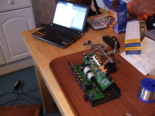
I've decided to take the plunge and have a go at modifying (modding) my Beresford DAC. There's a few threads out there that cover this......but I hope to produce a blow by blow guide for the electronics amateur (such as myself).
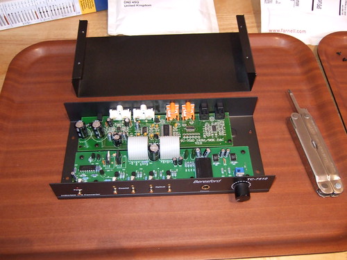
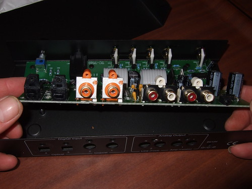
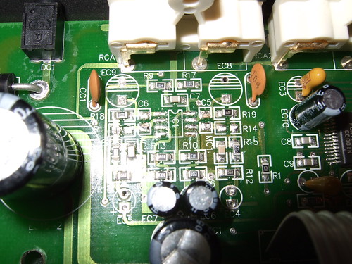
Inside the box
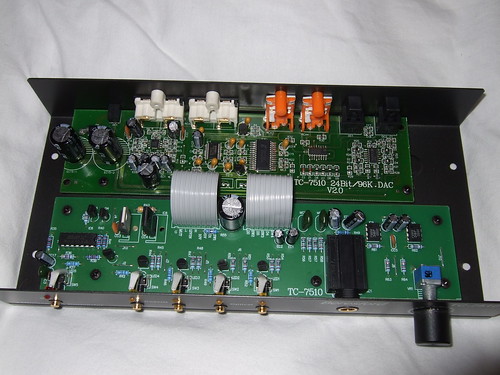
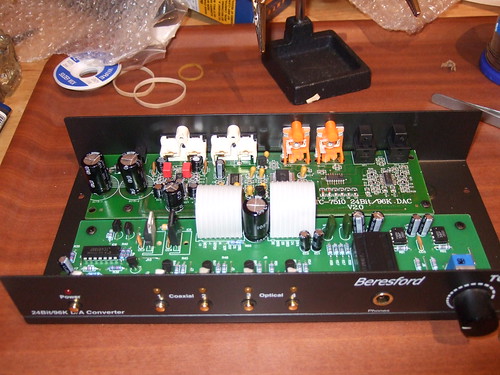
Beresford TC-7510 DAC Internals
This next bit is my interpretation of the internals and could be cobblers, so take it with a pinch of salt.
The board at the back is the DAC itself. On the very left are a couple of big capacitors which form part of the DC power input stage. Then there is the signal output stage which amplifies the analogue signal for the variable and fixed outputs. To the right of signal output stage are the actual DAC components.
The board at the front contains the bulk of the DC power input stage components (left), power switch, input selection, headphone amplifier and volume pot for controlling the headphone amp volume and the variable signal output.
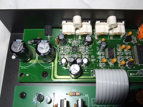
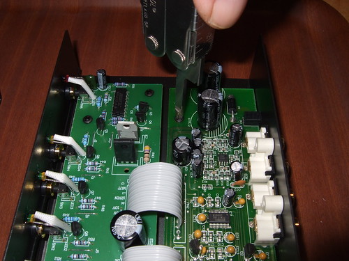
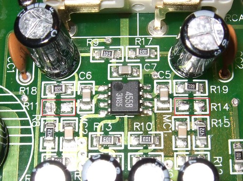
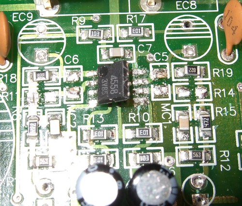
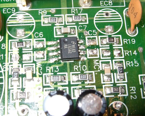
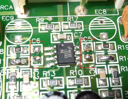
Beresford TC-7510 DAC Output Stage
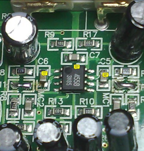
Beresford TC-7510 DAC Output Stage - closer
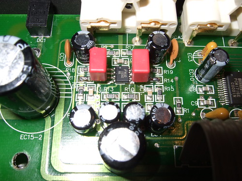
In the middle of the signal output stage you can see the surface mounted opamp (JRC4558) surrounded by surfaced mounted resistors and capacitors, radial electrolytic capacitors and, what look to me to be, a couple of ceramic capacitors (CC1 & CC2).
The Modifications
The first modifications (mods) I'm going to perform have the support of the designer. Stanley has produced a couple of .pdf files to document these mods and has discussed them on another forum. These mods are called Mod 21 and Mod 21 Pt 2. These mods focus on changes to the signal output stage.
However, if I do any other tweaks to the DAC, I'll use this thread to document them. Clearly, I'd be interested to read about the mods other people have performed and would encourage them to use this thread as well to keep them all in the same place.
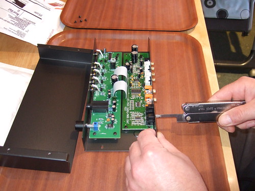
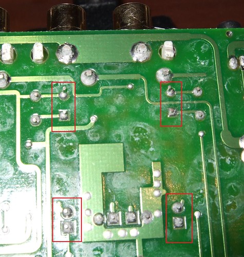
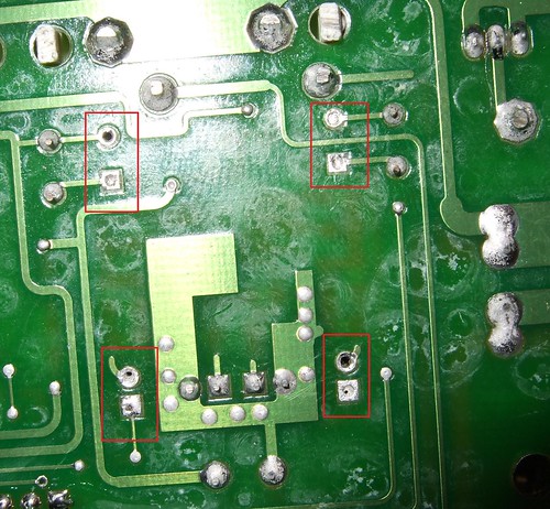
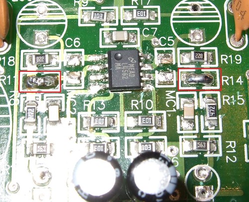
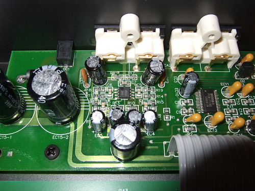
Mod 21
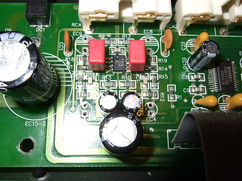
Mod 21
Refering to the photo above, this mod removes the resistors at R11 and R14 and replaces them with a solder bridge and replaces the four identified electrolytic capacitors with 47uF / 16V rated versions.
The solder bridge is effectively free. I have ordered the four capacitors from Audio Upgrades and have gone for these.

4 x Rubycon ZA 16V 47uF. Cost = £7.60.
On the face of it this mod should be fairly easy to do and doesn't really give me any cause for concern.
The pdf by Stanley is available here.
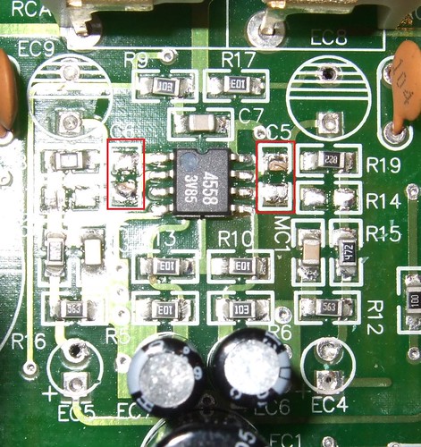
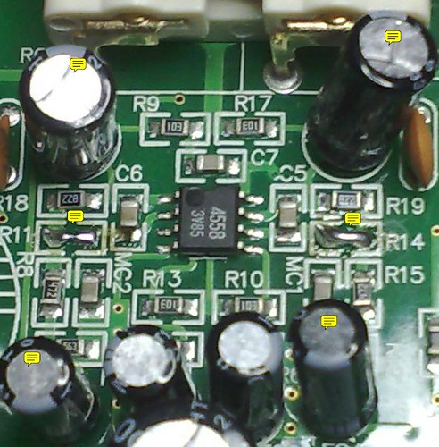
Mod 21 Pt 2
Mod 21 Pt 2
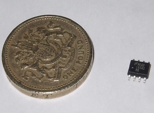
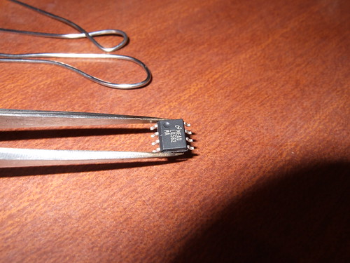
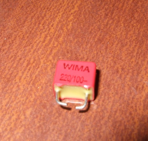
Refering to the photo above, this mod replaces the JRC4558 opamp with a National Semiconductors LM4562MA opamp and replaces the decoupling capacitors at C5 and C6 with a couple of WIMA 220pF/100v polypropolene capacitors.
I have ordered the replacement opamp from Audio Upgrades which can be found here. I'll get the WIMA caps from Maplins which can be found here.

1 x LM4562MA Opamp. Cost = £5.49

2 x WIMA 220pF/100v. Cost = £0.30p
This mod is a different league to the first with the potential to brick the DAC. Removing the old opamp will be difficult enough. Soldering the new one in will be just as hard...maybe more so. I'm a bit worried about this one. Still, nothing ventured....
The pdf by Stanley is available here.
I'll update the thread as and when the components arrive and the work progresses. Now, where was I with that headphone amp thread....?
Inside the box
Beresford TC-7510 DAC Internals
This next bit is my interpretation of the internals and could be cobblers, so take it with a pinch of salt.
The board at the back is the DAC itself. On the very left are a couple of big capacitors which form part of the DC power input stage. Then there is the signal output stage which amplifies the analogue signal for the variable and fixed outputs. To the right of signal output stage are the actual DAC components.
The board at the front contains the bulk of the DC power input stage components (left), power switch, input selection, headphone amplifier and volume pot for controlling the headphone amp volume and the variable signal output.
Beresford TC-7510 DAC Output Stage
Beresford TC-7510 DAC Output Stage - closer
In the middle of the signal output stage you can see the surface mounted opamp (JRC4558) surrounded by surfaced mounted resistors and capacitors, radial electrolytic capacitors and, what look to me to be, a couple of ceramic capacitors (CC1 & CC2).
The Modifications
The first modifications (mods) I'm going to perform have the support of the designer. Stanley has produced a couple of .pdf files to document these mods and has discussed them on another forum. These mods are called Mod 21 and Mod 21 Pt 2. These mods focus on changes to the signal output stage.
However, if I do any other tweaks to the DAC, I'll use this thread to document them. Clearly, I'd be interested to read about the mods other people have performed and would encourage them to use this thread as well to keep them all in the same place.
Mod 21
Mod 21
Refering to the photo above, this mod removes the resistors at R11 and R14 and replaces them with a solder bridge and replaces the four identified electrolytic capacitors with 47uF / 16V rated versions.
The solder bridge is effectively free. I have ordered the four capacitors from Audio Upgrades and have gone for these.
4 x Rubycon ZA 16V 47uF. Cost = £7.60.
On the face of it this mod should be fairly easy to do and doesn't really give me any cause for concern.
The pdf by Stanley is available here.
Mod 21 Pt 2
Mod 21 Pt 2
Refering to the photo above, this mod replaces the JRC4558 opamp with a National Semiconductors LM4562MA opamp and replaces the decoupling capacitors at C5 and C6 with a couple of WIMA 220pF/100v polypropolene capacitors.
I have ordered the replacement opamp from Audio Upgrades which can be found here. I'll get the WIMA caps from Maplins which can be found here.
1 x LM4562MA Opamp. Cost = £5.49
2 x WIMA 220pF/100v. Cost = £0.30p
This mod is a different league to the first with the potential to brick the DAC. Removing the old opamp will be difficult enough. Soldering the new one in will be just as hard...maybe more so. I'm a bit worried about this one. Still, nothing ventured....
The pdf by Stanley is available here.
I'll update the thread as and when the components arrive and the work progresses. Now, where was I with that headphone amp thread....?