DIY Dual Mono Power Amps

Page 4 - Seeking answers? Join the What HiFi community: the world's leading independent guide to buying and owning hi-fi and home entertainment products.

PJPro

New member
Jan 21, 2008
274
0
0
Visit site
Momentary Pushbutton Switch Circuit with Sensing Loop

Initially, I didn't want a switch on the front of the power amps. However, given the soft start circuits, it seemed best to provide them. Indeed, the soft start circuit does support remote triggering, e.g. by a pre-amp, but let's not go there.

So, if I was to provide switches I wanted them to be nice like the Bulgin vandal-resistant series.

MPI1002_400px.jpg

Buglin Anti-vandal Switch

As it happens AMB provides a PCB to support momentary pushbutton switchs. This is the Epsilion 24 (e24). This neat little board also provides dual LED support for the switch (to provide an indication of fault conditions) and supports thermal sensor arrays.

The e24 requires its own dedicated power supply. This can be provided by a miniature transformer and a PCB, the Sigma 24 (s24), is also provided by AMB.

I won't go into the workings of the e24, but essentially it allows the switch to be used to activate an off board relay. This relay breaks the live connection to the soft start circuit. The e24 also has an additional onboard relay which is triggered by devices on the sensor loop. When the sensors are triggered, they cause the onboard relay to act as though the switch had been pushed and switch off the power to the amp.

The sensors I have chosen are thermal devices. They are very much like switches and can be fixed onto heat sensitive components. They are ordinarily open (off). When a threshold temperaure is reached they close (on) and trigger the relay to turn off the amp. The plan is to attached the sensors onto the chips. I have selected variants which close at a temperature which is within the safe upper bound temperature of the chip.

Pg_046.jpg

Thermal Switch

I have built the e24 and s24, so here are a few pictures.....
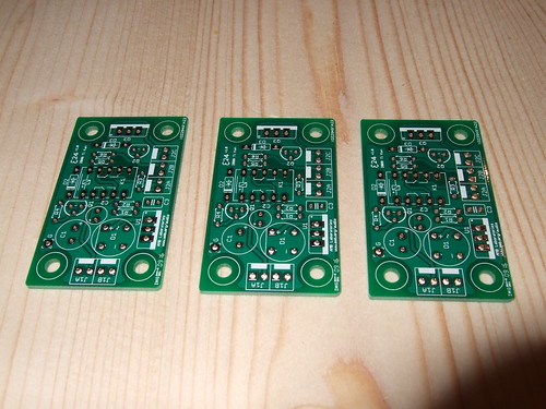
3875100633_e493e85b66.jpg

e24 PCBs

I've got three of these boards; one for each power amp and one for the pre-amp. Not sure which pre-amp I'll build yet. Something with valves might be nice.

3875892296_62888da242.jpg

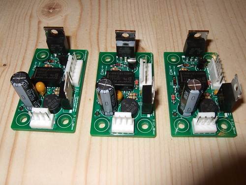
e24 PCBs populated with components.

The e24s were easy to build and no issues were encountered along the way. That said, I haven't actually tested them yet.
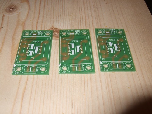
3875894276_b8de5e104e.jpg

s24 PCBS.

Here are the corresponding three s24 PCBs....one per e24.

3875107101_183b4cc66a.jpg

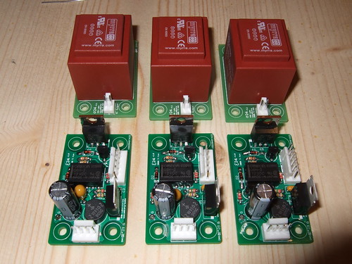
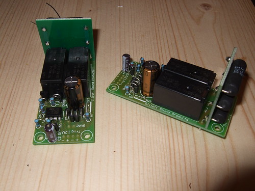
e24 and s24 PCBs populated with components.

Again, no issues with construction to report.

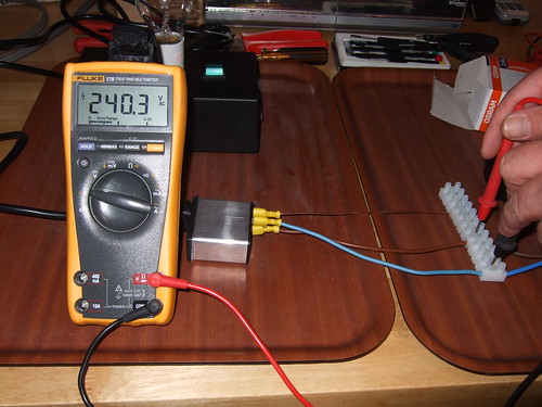
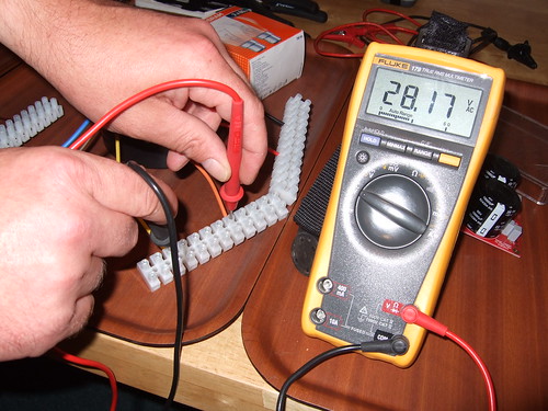
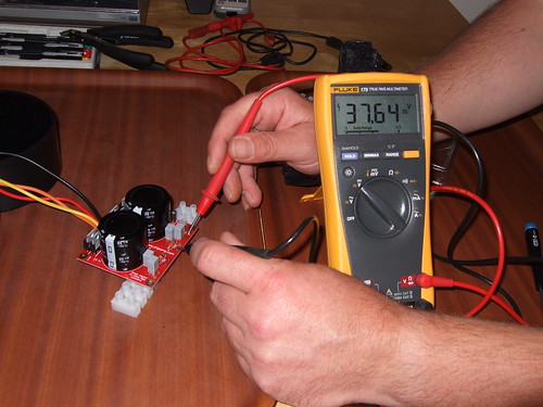
The transformer provides 12VAC. The rectifier to convert AC to DC is held on the e24. After rectification, about 17VDC is provided. A regulator is used to drop this down to the required 12 VDC. A stable voltage, as provided by the regulator, is required to prevent false triggering of the circuitry because fluctuations in voltage can fool the circuit into thinking the pushbutton switch has been pressed.

3875108861_e74b99913a.jpg

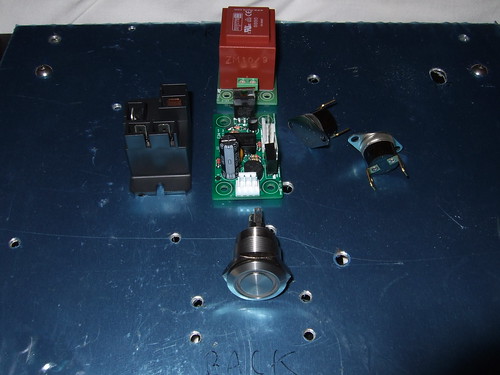
Power switch components for one amp.

So, in the centre is the e24 with the s24 directly behind it. To the left of the e24 is the relay which switchs the main power supply to the soft start circuit. To the right are the thermal sensors. At the front is the push button switch.

The e24 is designed to sit on top of the s24, making for a much more compact component.
 

PJPro

New member
Jan 21, 2008
274
0
0
Visit site
Here's a picture of the completed soft start modules. You can see the bank of resistors on the upright PCB. These resist the flow of current into the primary transformer while the timing capacitor is charging. It's the small one right on the front edge of the main PCB.

You can also see the relays (black boxes) on the main PCB. When the timing capacitor is charged, the relays are activated causing the bank of resistors to be short circuited thereby providing full current to the primary transformer.

3884403985_a2fe35a88a.jpg


From the lack of questions, should I assume you are all getting this or is it all gooble-de-****?
 

PJPro

New member
Jan 21, 2008
274
0
0
Visit site
daveh75:Nope, understood it so far
emotion-21.gif


Thanks daveh75. That's good. There's no point me blathering on if no-one gets what I'm on about.
 

PJPro

New member
Jan 21, 2008
274
0
0
Visit site
Primary Transformer

I've said quite a bit about this transformer previously in the thread. Anyway, suffice to say that the job of the transformer is to take mains (or primary) 240VAC and convert it to some lower voltage (secondary). In this instance, it's 25VAC. The transformer provides dual secondaries so there are two pairs of wires coming out with each pair providing 25VAC.

I'm not going to go into the detail of how the transformer manages to do what it does but it's basically to do with the ratio of turns or windings between primary and secondary wire coils around an core. If the ratio is one to one you'll get the same voltage out of the secondary as you put into the primary (assuming 100% efficiency). If you have half as many secondary windings, the voltage is reduced by half.

Take a look here for more information.
 

PJPro

New member
Jan 21, 2008
274
0
0
Visit site
Power Supply Module

The power supply module has a few jobs to do. It converts AC to DC. It acts to reduce ripple in the resulting DC. It removes noise in the DC.

AC (and voltage) is described by a sine wave (see below). The values of this sine wave alternative between positive and negative in a path which reflects the changing sine values of the angles created by the 360 degree rotation of a radius around the circumference of a circle over time. The amplitude of the sine wave reflects the diameter of the circle, while the height of the peaks reflect the radius.

One full rotation around the circle (from zero to the positive peak, back to zero, onto the negative peak and back to zero) is called a cycle. In the UK, the frequency of cycles (hertz) is 50.....so 50 complete rotations of the circle every second.

AC is measured as a root mean square (RMS). All of the values in a complete cycle of a sine wave are squared. This serves to make all values positive. The mean is then calculated and then square rooted to remove the squaring applied but retaining positive conversion of the values. Given this is a mean, one would expect the peak values to be higher.

The peak value can be calculated using the crest factor or peak-to-average ratio. For a fully rectified sine wave the crest factor is the square root of 2. The following equation

Crest Factor = Peak / RMS

can be rearranged to isolate the Peak by multiplying through by RMS giving

Crest Factor x RMS = Peak

The primary transformer provides 25VAC. Remember, this is a RMS. So the positive peak is

sqrt(2) x 25 = 35.4 volts

Of course, the AC sine wave is positive and negative so the peaks are +/- 35.4VAC giving a full range of 70.7 volts.

The AC is converted to DC by the bridge rectifier. This comprises of 4 diodes which are arranged to convert the negative part of the sine wave to positive (see below). The resulting DC is measured in a different way to the AC. It is the peak value which is quoted. So 25VAC provides 35.4 VDC (the AC peak value). This assumes a 100% efficient bridge rectifier. In practise, a little voltage is lost to the diodes.

Gratz.rectifier.en.png


You'll notice that the DC is decidedly wobbly rather than a constant value. This is termed ripple and is a reflection of the AC origins of the DC. Ripple is bad for audio. So, how to get rid of it? The most common approach is a place large smoothing capacitor just after the bridge rectifier. This discharges to fill the troughs between the peaks but its effectiveness reduces before the next peak is reached, resulting in a smaller ripple. The module I've built uses this approach.

One further enhancement would be to place a voltage regulator after the smoothing capacitors. This provides a constant voltage but this is usually a little lower the voltage it is provided. So feed it a wobbly 35.0 volts, it'll maintain a near constant 33.0 volts with the excess voltage being burnt off as heat.

Phew!
 
A

Anonymous

Guest
I give up.......lets see what you get when you measure the voltage after you have built it.....

30+ years in electronics and I still dont see how a rectifier can give out more DC then the ingoing AC......
 

PJPro

New member
Jan 21, 2008
274
0
0
Visit site
Actually, the reason I went into so much detail was to try and satisfy you that my argument was sound. I double checked my reasoning with an senior electronics engineer / designer at work before posting.

Let me make one thing absolutely clear. There is not more voltage being producted by the bridge rectifier. It's the way that AC and DC are measured. If we measure AC by the peak voltage (rather than by the industry standard of root mean square) the DC voltage produced is the same (assuming a 100% efficient bridge rectifier). In reality, the bridge loses a little voltage, so the DC produced is slightly less than the AC peak.

But I will definately do an experiment and report back as part of this thread.
 
A

Anonymous

Guest
Quote your words...

The primary transformer provides 25VAC. Remember, this is a RMS. So the positive peak is sqrt(2) x 25 = 35.4 volts

Of course, the AC sine wave is positive and negative so the peaks are +/- 35.4VAC giving a full range of 70.7 volts.


So you start with a transformer giving 25 VAC.....which as you say is RMS, OK thats cool........How in gods name does that then get bumped up to 70.7V. By your own words and quite correctly you have said that the measured voltage is the RMS value of the peak to peak voltage. So we have a -ve peak and a +ve peak with a peak to peak voltage of 35.4V (without bothering to work it out myself I would say is about right).

You have already taken into account the voltage peaks so please explain the reasons for the last statement shown above. By that reconing we would all have somewhere near 460 VAC RMS on our mains wiring.....

An interesting statement from your last post, and I quote. In reality, the bridge loses a little voltage, so the DC produced is slightly less than the AC peak. A complete change in direction to that which was posted above and on the Cambridge PSU thread where you were adamant that the DC out was more than the AC in
.

Thats it...i've done my best . I wont post or comment again.....
 

PJPro

New member
Jan 21, 2008
274
0
0
Visit site
I'm disappointed and, I'll admit, slightly frustrated that I am unable to convince you of my arguments. However, I'm not one for giving up so.....

raym87:
So you start with a transformer giving 25 VAC.....which as you say is RMS, OK thats cool........How in gods name does that then get bumped up to 70.7V. By your own words and quite correctly you have said that the measured voltage is the RMS value of the peak to peak voltage. So we have a -ve peak and a +ve peak with a peak to peak voltage of 35.4V (without bothering to work it out myself I would say is about right).

Let me use mains AC as an example. The quoted RMS for mains ac is 240V. Using the crest factor we can see that the positive peak AC is

240 x sqrt(2) = 339.4 VAC.

Over one full cycle, the AC sine wave provides a positive peak and a negative trough. This peak and trough are +339.4 VAC and -339.4VAC respectively. So the full range of volts produced (peak to trough) is 678.8 VAC. This is the range of values and reflects the amplitude of the sine wave i.e. if we count the volts from -339.4 through to +339.4 we arrive at 678.8.

raym87:
You have already taken into account the voltage peaks so please explain the reasons for the last statement shown above. By that reconing we would all have somewhere near 460 VAC RMS on our mains wiring.....

That is due to the nature of the RMS. Remember, the RMS is the root mean square. If the squaring and root were not performed, the mean for any sine wave would be zero i.e. the peaks and troughs would cancel themselves out as they oscillate around zero. The squaring and rooting effectively reduces the range of values by half, i.e. it makes the negative values positive. This is simply a mathmatical technique to produce a meaningful, errrr, mean.

raym87:
An interesting statement from your last post, and I quote. In reality, the bridge loses a little voltage, so the DC produced is slightly less than the AC peak. A complete change in direction to that which was posted above and on the Cambridge PSU thread where you were adamant that the DC out was more than the AC in.

I've taken a look at my comments above and have provided my comments from the DAC Magic thread below.

PJPro:Well, the regulator in the DM will need to work harder to arrive at the required internal voltage required if it starts with 12VAC.....and will have to burn this off as heat.

If you're interested, the 12VAC after rectification (conversion to DC) will be 12 x 1.4 = 16.8VDC. This would seem way high if only 5VDC are required and the regulator is going to be working very hard to get the 16.8 volts down to 5......and burning off a lot of heat in the process.

If you use a 9VAC supply, after rectification you'll have 9 x 1.4 = 12.6VDC. This still seems a little high if the target voltage is 5VDC?
PJPro:No, they've always done this. To calculate the VDC from VAC after rectification you multiply by 1.414 or, more precisely, the square root of 2.
PJPro:Try this....Clicky

This page attempts to explain the basics. Here's an extract.....

AC voltages are specified in RMS (Root Mean Squared). But rectifying circuits with smoothing capacitors produce a DC voltage that is close the peak value of the AC input, which is bigger than the RMS value by a factor of 1.414 (the square-root of 2).

I'm in the process of making some power amps. As a test, I will measure the DC after the bridge and post the results.
PJPro:Agree with your statements and, yes, I would be surprised if the DM used half wave rectification. Indeed, even the most basic of amp designs would use full wave rectification.

But I think you're missing the point. Please read my extract again. Basically, the quoted AC provided by the transformer will be the root mean square AC (Vrms) not the peak AC. The DC produced on the rails will reflect the AC peaks NOT the quoted Vrms. Actually, it'll be slightly below the AC peaks due to losses by the diodes themselves.

I'll freely admit that I'm no expert...but the basic understanding is simple, isn't it?

I apologise if my comments have suggested or implied that the bridge can somehow increase the voltage produced and you are absolutely right to say that 4 diodes are unable to perform this function.

From my perspective, I don't believe I have been adamant that more DC is produced than the AC provided and that my comments have been consistent throughout my postings.

It is true to say that in places I have assumed a 100% efficient bridge. I should have clarified this point. I should also have indicated that the quoted AC is a RMS in my first posts on the matter....but at that point I didn't know that it was. Subsequent investigations have revealed to me the detail behind the rule of thumb I stated.

raym87:
Thats it...i've done my best . I wont post or comment again.....

raym87, I am grateful for your comments as they have caused me to question my own comments and made me investigate further to either retract or support them. So, you have caused me to understand more about AC and DC than I would have done otherwise. For this, I offer my thanks.

Please do not refrain from posting further. I am sure that together we can bottom this one out and come to a common understanding. I would also welcome comments from third parties. Perhaps I am talking rubbish and I just can't see it?
 

PJPro

New member
Jan 21, 2008
274
0
0
Visit site
I've been a bit concerned with the regulator on the switch circuit. As stated above, the voltage coming in (after the bridge) will be 17 VDC. This needs to be dropped to 12 VDC. The current used by the offboard relay coil is 77 mA. With the other stuff I've rounded that up to 100mA.

So, the regulator will be attempting to dissipate 5V x 0.1A = 0.5W. I was slightly worrried that this would damage the regulator and a heatsink would be required to assist.

Discussions with the designer (AMB) have reassured me that it should be alright and he has informed me that the regulator has a heat protection circuit which should turn it off if it gets too hot.
 
A

Anonymous

Guest
OK....temporarily retracting the last line in my last post I will post a reply in the hope that I can clear up the points of disagreement.

We both agree thar ACV is measured as the +ve and -ve components of an AC waveform...yes?

RMS voltage is extrapolated from the peak to peak measurements....yes?

So if the measurements are made from peak to peak, then they are taken using the +ve AND -ve part of the waveform. The -ve peak and the +ve peak

Lets not complicate this by using PP and RMS in this example below...just call it ACV to make life easier OK.

Therefore an AC voltage of say 240V is the value of the FULL AC waveform..NOT the +ve component on its own and NOT the -ve component on its own..a PEAK to PEAK.

Therefore the value of the +ve part is ACV/2 and the -ve part is ACV/2 as well. Or 0 to 120V +ve and 0 to 120V -ve.

So what we have is an AC cycle measured from the highest point on the +ve peak to the lowest point on the -ve peak. The RMS value is then extraoplated from that. RMS = PtoP x 0.7071. If you want to go back to P to P then use 1.4xxx.

Where you have been making a mistake is in taking the AC measurement and assuming that it is for either the +ve OR -ve part of the waveform. It is NOT, it is for a FULL cycle from 0V to +ve peak down again to 0V through to the -ve peak and back up again to 0V.

I hope that clears it. I have tried to explain as best I can.
 
A

Anonymous

Guest
idc:We need a judge to decide on the winner of this debate.
emotion-2.gif
Anyone else know stuff about electricity? Or will we have a three way debate then?

No judge required. The laws of physics have spoken.......
emotion-5.gif


Anyways...its not a competition......
 

PJPro

New member
Jan 21, 2008
274
0
0
Visit site
raym87:
OK....temporarily retracting the last line in my last post I will post a reply in the hope that I can clear up the points of disagreement.

OK. Good. Thanks for your patience.

raym87:
We both agree thar ACV is measured as the +ve and -ve components of an AC waveform...yes?

RMS voltage is extrapolated from the peak to peak measurements....yes?

So if the measurements are made from peak to peak, then they are taken using the +ve AND -ve part of the waveform. The -ve peak and the +ve peak

Yes, absolutely. The RMS takes into account the positive and negative values of the sine wave.

raym87:
Lets not complicate this by using PP and RMS in this example below...just call it ACV to make life easier OK.

Therefore an AC voltage of say 240V is the value of the FULL AC waveform..NOT the +ve component on its own and NOT the -ve component on its own..a PEAK to PEAK.

Therefore the value of the +ve part is ACV/2 and the -ve part is ACV/2 as well. Or 0 to 120V +ve and 0 to 120V -ve.

So what we have is an AC cycle measured from the highest point on the +ve peak to the lowest point on the -ve peak. The RMS value is then extraoplated from that. RMS = PtoP x 0.7071. If you want to go back to P to P then use 1.4xxx.

Where you have been making a mistake is in taking the AC measurement and assuming that it is for either the +ve OR -ve part of the waveform. It is NOT, it is for a FULL cycle from 0V to +ve peak down again to 0V through to the -ve peak and back up again to 0V.

OK. Now I think we are getting to the nub of the matter. You believe the AC voltage is +/- 120 volts. You state the following

RMS = PtoP x 0.7071

If we divide though 0.7071, we get

RMS / 0.7071 = PtoP

Therefore....

240 / 0.7071 = PtoP = 339.4

Therefore, each peak must be half 339.4 or +/- 169.7 VAC. Given this information, we can work out the RMS using first principals by multiplying the sine of each angle by the peak. This will create the sine wave for us. The RMS equals all values of the sine wave. Each value is squared. The mean is taken of these values. The mean is then square rooted to arrive at the RMS.

So, here follows a table which creates a sine wave of +/- 169.7 VAC.

DegSineWaveWave2
00.000.00.0
360.5999.79949.5
720.95161.726048.1
1080.95161.726048.1
1440.5999.79949.5
1800.000.00.0
216-0.59-99.79949.5
252-0.95-161.726048.1
288-0.95-161.726048.1
324-0.59-99.79949.5
3600.000.00.0
Mean13090.0
RMS114.4

You'll see that using first principals shows that the RMS equals 114.4 VAC. OK, so we don't have all possible values in the wave...so there will be a disproportionate affect on the mean by the zeros but whatever we do, it's unlikely to get up to 240 VAC....which is the RMS we are after.

I repeated the above exercise using my proposed values. I believe the positive peak is + 339.4 and the negative peak is - 339.4. So, multiplying the sine values by 339.4 gives....

DegSineWaveWave2
00.000.00.0
360.59199.539797.9
720.95322.7104192.5
1080.95322.7104192.5
1440.59199.539797.9
1800.000.00.0
216-0.59-199.539797.9
252-0.95-322.7104192.5
288-0.95-322.7104192.5
324-0.59-199.539797.9
3600.000.00.0
Mean52360.2.0
RMS228.82

Again, the RMS isn't equal to 240 but I think you'll agree it's a lot closer.

I repeated the above using each degree over the sine wave and the results were an RMS of 119.8 VAC and an RMS of 239.7 VAC.

Perhaps I am still misundertanding but the maths, coupled with a foray into first principals, would tell me that for an RMS of 240 VAC, the peak voltage is 339.4 VAC and the peak to peak voltage is 678.8 VAC.

raym87:
I hope that clears it. I have tried to explain as best I can.

To back up my claims further, I tried to find an unequivocal statement from a british authority e.g. .gov.uk or something but I couldn't find one.
 
A

Anonymous

Guest
I give up....................................................
 

PJPro

New member
Jan 21, 2008
274
0
0
Visit site
OK. The only recourse then, is practical experiment. I'll try and do something tonight. My transformer produces a RMS of 25 VAC. After rectfication (and smoothing), I expect this to produce 25 * sqrt(2) = 35.4 VDC or there abouts. There should be some loses due to the diodes in the bridge (0.7 VDC each?) so around 33 VDC.

So I'll state my null hypothesis....

25VAC will produce approx 33 VDC after rectification and smoothing.

The experiment will serve to reject or accept this hypothesis.
 

PJPro

New member
Jan 21, 2008
274
0
0
Visit site
OK. The results are in........

In the first picture you can see my rig, which comprised of an IEC power inlet module, a 160 VA transformer and a power supply module with onboard bridge rectifier and smoothing capacitors.

3893521931_2c3622a421.jpg

Test Rig.

My first test was to ensure that the correct voltage was being provided by the power inlet module. The reading I was able to take was 240.3 VAC. Remember, this is the RMS value. It's a pity at this point that my Fluke doesn't allow the measurement of peak and peak to peak values....but there you go.

3893524065_24ea7c3129.jpg

Mains VAC (RMS).

The next step was to measure the VAC (RMS) being produced by the transformer. I was slightly surprised that this was 28.2 VAC.

3893525861_0393683cf5.jpg

Secondary VAC (RMS) produced by transformer.

This is three volts more than I was expecting and will impact the H0. Therefore, I will need to restate the H0 to match the available voltage.

So, 28.2 * sqrt(2) = 39.9 VDC. Each diode will lose about 0.7 VDC and there are four of them, making 0.7 x 4 = 2.8 VDC. So the expected VDC is 39.9 - 2.8 = 37.1.

H0: 28.2 VAC will produce approx 37.1 VDC after rectification and smoothing

The final picture shows the measured VDC at the output of the power supply module. Is is a little higher than I would have expected at 37.64 VDC but in my opinion it is near enough to allow H0 to be accepted.

3894317102_3984c2afe8.jpg

VDC after full rectification and smoothing.

I have exhausted all possible further avenues for proving my argument...except finding that documented statement from a government (or similar) site. I spent some time trying to find this today and had to give up (the kids were bored). However, I am satisfied that the theory, foray into first principals and now the supporting data present a pretty convincing argument.

However, I am still open to further debate and accept my experience is limited.
 
A

Anonymous

Guest
I will try to clear the confusions.

1. AC voltage is very often quoted in RMS. It can also be quoted "peak to peak value" or "+/- value". 25 VAC RMS can be quoted as:
a) 25VAC RMS
b) +/-35 V
c) 70 V p2p
If you look at 25 V AC on the oscilloscope you will see a curve which crosses 0, reaches 35 Volts, then down to 0, down to -35 Volts and so on. Peak to peak this is 70 volts. Peak is +/- 35 volts. RMS it is 25 Volts.

2. Your transformer will give you much more than 25 volts AC because you forgot to add (a) regulation and (b) the 230V spec. Most transformers are wound for 230V to sit between 220 V European outlets and 240 V UK mains. Therefore in the UK you will get more than 25V AC and in Europe you will get less. Additionally you forgot to add regulation. As you draw more current from the transformer its internal resistance plays a part and the voltage drops. The more current you draw the more the voltage drops. The manufacturer quotes 25 Volts AC secondary as the worst case scenario, when the transformer is fully loaded to its maximum specification. But when you measure it with your meter, or when it is powering your precious amplifier which is idle, the voltage is increased as there is no load. Regulation is expressed in a % and it is typically larger for small transformers and smaller for big ones. From the top of my head I think a 160VA transformer would haave something like 7% regulation. Therefore at no load the voltage you would be seeing would be something like: 25 * 240 /230 * 1.07 = 27.91 V. If you rectify that you will be getting 39.5V DC on each rail, almost 80 volts across your two rails. This is very important because these (unexpected) voltages may easily destroy your electronics (eg the LM3886).
 

PJPro

New member
Jan 21, 2008
274
0
0
Visit site
Thanks akis. Good to get a third view.

akis:
If you rectify that you will be getting 39.5V DC on each rail, almost 80 volts across your two rails. This is very important because these (unexpected) voltages may easily destroy your electronics (eg the LM3886).

Thanks for the warning but I assume that I am well within tolerances for the LM3886.
 

PJPro

New member
Jan 21, 2008
274
0
0
Visit site
Disconnecting Network

Within audio equipment there are two grounds. These are signal and power ground. Audio designers usually like to keep these as separate as possible as noise from the power ground can pollute the signal ground. However, when these are connected directly to Safety Earth the result can be ground loops.

So what is a ground loop? Consider a CDP and an amp. Each are connected to earth in the wall via their mains plug. When you run electrical interconnects between the CDP and amp a local loop is created eg one can trace a connected path from the CDP through to the amp via the interconnect, through the signal ground in the amp to the Safety Earth, down the mains cable to the wall socket, along the earth wire to the CDP mains socket, up the mains cable to the CDP Safety Earth and into the signal ground.

What travels around this loop? Current created by, for instance, stray magnetic fields. These fields are generated by the transformers in the connected audio equipment. This circulating current gives rise to the characteristic hum in audio equipment and hum bars in video.

To overcome ground loops, a number of strategies can be adopted.

Firstly, something basic. You can disconnect the earth wire in the plug of either the CDP or amp. Alternatively, one can use a plug with a dummy (plastic) pin. People do actually do this and it does work. But what you are left with is a real risk of electrocution or fire.

Let's say a stray wire in the equipment with the removed earth comes detached and contacts the case. A sudden, massive spike in current will rush into the power/signal circuit and attempt to run to earth through the interconnects and into the equipment which is still connected to mains earth. These interconnects, which are not designed to handle the current involved, are highly likely to cause a fire. If you are unlucky, somewhere a component may fry breaking the path through the signal ground leaving you with a live case waiting to (possibly) kill you.

Another strategy is to "lift" the signal ground above the Safety Earth. To do this one connects all of the grounds in the equipment to a single point (star ground) and then place a resistor between ths point and the Safety Earth. This resistor serves to resist the circulating current travelling around the local loop and prevents the hum.

Again, however, should a fault occur on the PCB, the current will rush through the resistor which is likely to fail. We are then back in a similar situation as before. So, this approach is not generally recommended although you will see it being used in the DIY community.

The disconnecting network is similar to the resistor approach but uses more robust components which are ensured to survive the currents involved during a fault. Consider the picture below.

3780878649_62fe729f70.jpg

Disconnecting Network

The Safety Earth attaches the earth wire from the mains cable to the case. The zero volt line connects the network to the star ground. During normal operation the resistor lifts the internal ground and prevents the loop. The cap helps reduce noise. The diode bridge provides two paths to earth in the event of a fault. So, if one path fails there is another as backup. Moreover, the bridge contains very solid conductors making failure unlikely. The switch allows the disconnecting network to be bypassed (if a ground loop is absent) but still provides a route for the fault current to Safety Earth via the bridge.

This latter option seemed to be a pretty good to me and if it's good enough for Bryston (I've seen Bryston schematics which include exactly the same components as the disconnecting network), it's good enough for me!
 

TRENDING THREADS

Latest posts