DIY Dual Mono Power Amps

Page 3 - Seeking answers? Join the What HiFi community: the world's leading independent guide to buying and owning hi-fi and home entertainment products.

PJPro

New member
Jan 21, 2008
274
0
0
Visit site
I've noticed that a number of experienced DIYers recommend building a tool for testing power supplies. This, apparently, gives you an early indication if you've done something silly. The tool is a box with a light bulb on top and a couple of switches. I'm not altogether sure I understand how it works, but it is simple enough to build.

The PSU test tool I'm going to build is this one.

bulb_tester.jpg

Nuukspot's Bulb Tester
 

idc

Well-known member
That is just an excuse to keep building stuff. Next it will be a test tool to test the test tool! The site you linked to is scary, way too much red writing warning of deaths and explosions if you get it wrong.
 

PJPro

New member
Jan 21, 2008
274
0
0
Visit site
idc:That is just an excuse to keep building stuff. Next it will be a test tool to test the test tool!
Yes, I know. And I keep finding reasons to buy stuff too.

idc:The site you linked to is scary, way too much red writing warning of deaths and explosions if you get it wrong.
The only bit that dodgy is the wire going from the IEC socket to the transformer. This is 240v. However, I've got a strategy to sort this.

If you're really nervous, you could skip the PSU and use a wallwart. I've had a look at these but they get a bit pricy when you need 18-30v at 6A or above. But you could use a much smaller case (big saving). Not quite sure how you'd go about grounding though.....
 
A

Anonymous

Guest
@pjpro, lovely detailed commentary as ever, all being filled away in my head for sometime next year after we move house

The amp looks great so far thanks
 

PJPro

New member
Jan 21, 2008
274
0
0
Visit site
OK. So I've got my bits for the bulb tester (see below).

3699159132_9bfc643316.jpg

Bulb Tester bits

I'm going to use a plastic box, so I can forget the issues of grounding. What I hadn't considered was that I need components which did not have any metal parts which pierce the case. So, the IEC sockets and the lamp holder need to be changed. I'll go for clip-in versions of the IEC sockets and the sort of lamp holder than usually hangs by a wire from the ceiling.

The illumunated switches looked they were going to be a problem too (no markings) but I've had a clarification from someone about wiring these in.

As usual, I'll provide a narrative and pictures to cover construction as I go.
 

PJPro

New member
Jan 21, 2008
274
0
0
Visit site
Back to the main build.....

I needed to fit the feet and create the inner tray. After some careful marking out, I drilled four 5.5mm holes through the bottom of one of the cases. These were deburred using a 12mm drill bit.

3714267016_419ff2660f.jpg

Drilling holes...

3713457951_b2098a534e.jpg

Four new de-burred holes.

I then bolted the two bottom trays together, using holes which were already present in trays, to allow the first tray to be used as a template for the second. I used a similar technique for the inner trays except that clamps were used.

3713460729_e6ec7bd8d5.jpg

Using the first tray as a template for the second.

Now I need to prepare my little blocks of aluminium. The idea was that the feet would bolt into the bottom of the block, leaving enough space for the inner tray to be bolted on from the top....like a long nut. So, the first step was to drill the bar.

The thread projecting from the feet is 5mm wide. So, allowing for the thread itself, I needed to drill a 4.2mm hole.

3713463409_fa18e448cb.jpg

More drilling...

With the holes drilled, it was now necessary to create the thread. I used a tapered tap to start the thread off and finished the job with a plug or bottom tap.

3713465847_4b0661e3cc.jpg

Creating the thread.

All that remained to do for the blocks was to cut them from the bar and remove any burrs.

3713468403_6bdd4e3b0f.jpg

Spacer blocks coming off the bar.

Here's one of the trays with the feet fitted and the inner shelf in place. The inner shelf still has its protecive film attached. This will allow me to attach the PCBs, transformer, heatsink, etc, to the inner tray without having to put loads of holes in the bottom tray.

3713471405_c60940bb38.jpg

Bottom tray with feet and inner tray.
 

PJPro

New member
Jan 21, 2008
274
0
0
Visit site
I mentioned the Bulb Tester Tool earlier in this thread. Well, I've consulted the experts to understand how it works and build my own, based on the Decimal Dungeon version.

What does it do and how does it work?

Provided by pacificblue

Light bulbs are temperature-dependant resistors. The higher the temperature, the higher the resistance (PTC - positive temperature coefficient). That is, why they usually blow the moment, they are switched on. Their resistance is low then.

Now connect an amplifier in series and switch it on. The inrush current is high and will probably make the bulb light up for a short moment. If the amplifier is okay, there will not be much current draw after that -> low current through the lamp -> no heat, no light -> low resistance -> no voltage drop across the lamp -> full voltage at the amplifier. If the amplifier has a fault, it will draw a big current -> filament heats up, lights up -> resistance goes high -> high voltage drop across the lamp -> reduced voltage at the amplifier. There is your cheap and easy current limiter.


Provided by Redshift187

If the bulb is wired in series with the Live as it should be, all current must pass through the bulb. At low current, the filament will not heat much, and resistance will be low. As current rises, the filament heats, and resistance rises. It acts as both a current limiter and a warning device (if the bulb is full on, there may be a short). This protects your equipment (and you!) while allowing you to check voltages.

Hopefully, given the above statements, you'll understand what the thing does.

My summary would be that the tool is a current limiter which provides an indication of sustained high current demand over and above that expected for the device under test. This sustained demand indicates a problem with the device.

I'll provide details on the variants, from the most basic to the delux version I've made, in subsequent posts.
 

PJPro

New member
Jan 21, 2008
274
0
0
Visit site
In its most basic form the bulb tester is no more than a lamp holder which is placed in series on the live wire.

A more fancy version places a switch before the bulb to allow the current to be switched off rather than having to reach down to the wall socket to switch off the power. Handy if you need to act quickly!

The next variant places a switch across the bulb allowing the bulb to be shorted out. This allows the bulb to be taken out of the equation once the test has shown the device to be OK, without having to disconnect everything to plug the device directly into the mains. The illustration for this approach, as recommend by Decibel Dungeon, is posted above.

Finally, a further enchancement is to replace the push to make switches recommended by Decibel Dungeon with illuminated switches which provide an instance visual indication on the configuration of the tool.

I went for the latter version with illuminated switches. I had to didn't I.
 

PJPro

New member
Jan 21, 2008
274
0
0
Visit site
The BoM for the delux lamp holder is.....

ABS Box BZ75S
16A Rocker Switch Red GU55K
16A Rocker Switch Green GU56L
Euro Chassis Plug HL15R
Euro Chassis Socket FT63T
Insulated Crimps Blue JH82D
5A Terminal Blocks LR97R
Lampholder FQ02C

You'll also need some 5A twin and earth (to use for your hookup wire), earthing sleeve, a kettle lead and a lead with a Euro Line Plug at one end and a Euro Line Socket at the other.

My old PC had a lead which allowed the monitor to be powered from the PC. This is what you need for the last lead specified above. If you haven't got one, use a kettle lead and just change the wall socket plug for one of these.

Please note that the case I'm using is plastic...therefore I don't have to worried about earthing the case. One important consideration is that no metal parts must pierce the case. The plug and sockets which I use are designed to be screw/bolt attached. To get around this I have glued the plug and socket onto the case. Alternatively, one could use plastic bolts.

Just so we are clear, here's a picture of what we are trying to build. The brown wire is live, blue is neutral and green is earth.

3709620704_47146ea8d0.jpg

Bulb Tester connections.

OK, the first step is to drill a hole in the bottom of the case. I'm using a pillar drill and forstner bit here....but you could use a hand drill. This hole allows the lamp holder to be attached to the case.

3720866467_c45edab921.jpg

Drilling a hole for the lamp holder.

3720868983_e461ba58a6.jpg

Attaching the lamp holder.

Next to go in are the switches. These clip in place, so you need to ensure that the holes that you make are the right size.

3721685474_20cdcea9e0.jpg

Measuring the width of the hole required for the switches.

Mark out the holds on the case and then drill round the edge of hole, push/cut out the waste bit and file the hole square. Do the same for the other hole and then fit the switches.

3720874361_b3dbdd5a4f.jpg

Drill around the hole.

3720876869_3804bfc4e7.jpg

One hole complete.

3721693216_0f19c7f3e0.jpg

Switches fitted.

Do the same for the IEC sockets and glue in place. I used clamps hold everything together for an hour or so, to ensure a good bond.

The next thing to do is to start hooking up the components. I've used crimps here and a terminal block to make things easier. Also note the slack in the earth (yellow and green). You want this wire to be the last to become disconnected if there's any tugging on the wires. The power will be coming in from the left in the first picture.

3720882005_57869cbf59.jpg

Live connections.

3720884553_2dfa12c249.jpg

Earth and neutral connections.

The only thing that remains is to put on the lid (on the bottom) and the tool is complete. Please note which side the IEC plug and socket are on. It's important to get these round the right way.

3721700968_2de5b3bf9c.jpg

The power goes in this side from the wall socket.

3720889943_3f17c27b64.jpg


3721706742_4a5fc0b37e.jpg

And comes out of this side and attaches to the device under test.

I haven't tested my bulb tester yet as I can't find my PC to monitor power cable....so I'm probably going to have to make my own.

I'll demonstrate how the use the tool when testing my power amps.
 

PJPro

New member
Jan 21, 2008
274
0
0
Visit site
Slowy getting the bits together for the amps. The heatsinks arrived today. Hmmmmmm. Tasty. £13.34 delivered for both. They are 160mm wide, 40mm high and 50mm long.

3743193235_80a600775f.jpg

FISCHER ELEKTRONIK - SK 85/50 SA - HEAT SINK, 50MM, 1.4øC/W
 
A

Anonymous

Guest
Can't wait to see the finished product and find out how good it sounds!
 

PJPro

New member
Jan 21, 2008
274
0
0
Visit site
Got some new bits......

I wanted a elegant solution for the IEC power inlet, switch and fuse holders for these amps. These components form the bulk of the gubbins which are on the 240v side of the transformer, so I wanted it to be nice and easy.

I've gone for power inlet modules which combine all of the above components into a single unit. The particular model I have gone for also provides a RF filter. It's all packaged in a nice, shielded, aluminium case with all the internal bits fully enscapsulated. Oh, and it's a dual pole switch....meaning that both live and neutral are "broken" when you turn it off.

The fuse drawer has to be bought separately. It is possible to use dual fuses, but it has been pointed out that fusing both live and neutral is not recommended in the UK. If the fuse on the neutral blows, the device would appear to be off but potentially could still be shorting the case from the live. So, I had to get a fuse drawer which is provided with a shorting bar for the neutral side.

Anyway, I went for a Swiss made unit (Schurter). Really well made. Fab quality and a bit less than £20 each including fuse drawer. Note: the Standard Filter version is regarded as more suitable for audio than the Medical Filter version.

3772264039_f8308cbf9d.jpg

Schurter DD12.9121.111 Power Inlet Module with Schurter 4301.1413 Fingergrip Fuse Drawer (shorting bar in the neutral side).

3773072576_5bc8b103e7.jpg

Aluminium Shielding
 

PJPro

New member
Jan 21, 2008
274
0
0
Visit site
I might actually get round to putting some of this together soon. After all, I've got a new headphone amp arriving in August. Trouble is, I still don't have any speakers.
 
A

Anonymous

Guest
PJPro:Oh, and it's a dual pole switch....meaning that both live and neutral are "broken" when you turn it off.

The fuse drawer has to be bought separately. It is possible to use dual fuses, but it has been pointed out that fusing both live and neutral is not recommended in the UK. If the fuse on the neutral blows, the device would appear to be off but potentially could still be shorting the case from the live. So, I had to get a fuse drawer which is provided with a shorting bar for the neutral side.

Everybody got that?
emotion-7.gif


Good, let's move on then.
emotion-1.gif
 

PJPro

New member
Jan 21, 2008
274
0
0
Visit site
tractorboy:
Everybody got that?
emotion-7.gif


If you look at the picture called Aluminium Shielding (above) you can see the circuit diagram.

The power comes in from the LINE side. On the L (live) side you can see F1 (fuse) and another on the N (neutral) side (F2). These fuses are contained within the fuse drawer show in the first picture. The spring thing is the shorting bar.

The next component on the diagram, beyond the fuses, is the switch. You can see the two "gates" which isolate the LOAD side of the module from the LINE side.

Does this help?
 
A

Anonymous

Guest
I could nevr do that - good on you

However you may be able to help me - see my recent post on burn in issues with the beresford 7520

Stan did a factory upgrade with the op amps - I woudn't be in your league .

but I have bought an upgrade psu - the only trouble is I'm not sure what the polarity of the dac is and apparently the instructions on the psu upgrade box say I need to !

Does it matter ? or is it just plug and play ?

Cheers
 

PJPro

New member
Jan 21, 2008
274
0
0
Visit site
Errr, this is a bit outside of the scope of this thread......but my 7510 is positive on the inner contact. Double check with chebby.
 

PJPro

New member
Jan 21, 2008
274
0
0
Visit site
PJPro:......One important consideration is that no metal parts must pierce the case. The plug and sockets which I use are designed to be screw/bolt attached. To get around this I have glued the plug and socket onto the case. Alternatively, one could use plastic bolts.
.......
I was never very happy with the gluing, so took the opportunity to buy some nylon nuts and bolts when out shopping for bits for the power amps. Here's a piccy...

3792784661_57e565890b.jpg

Nylon nuts and bolts secure the IEC inlet
 

PJPro

New member
Jan 21, 2008
274
0
0
Visit site
A quick update with progress....

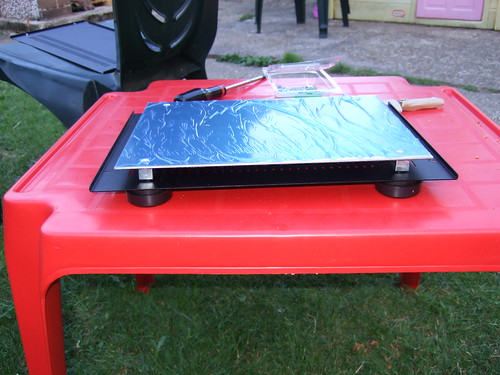
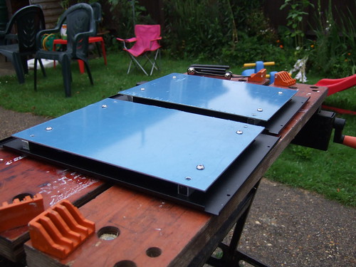
The feet I bought are rubbish. I've finally had to face that. Anyway, accepting that fact has made me rethink the false bottom. Rather than use those small aluminium blocks, I've used full length rails onto which to fix the false bottom.

3793602604_5b8a027b42.jpg

False bottoms fixed

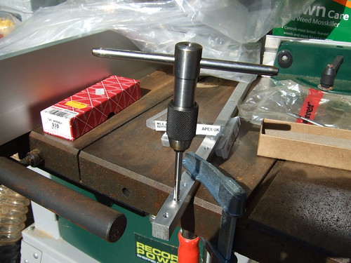
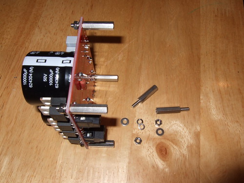
I needed to lay the components out on the false bottom to decide where to drill the holes to secure them in place. The first step towards this was to attach the standoffs to the PCBs.

3793603978_f423c5fffb.jpg

Fixing stainless standoffs to one of the Power Supply Units

Once all the standoffs were in place, I could start to arrange the components onto the false bottom until I found an arrangement I liked. The goal here was to minimise the length of the interconnecting wires and to keep the audio signal path away from the noiser elements of the amps e.g. the transformer.

3793605282_d593d190dc.jpg

Laying out the components.

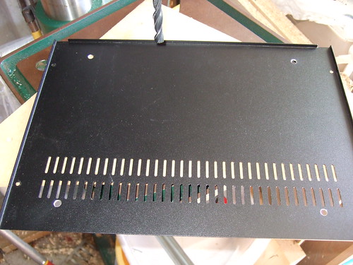
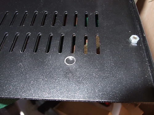
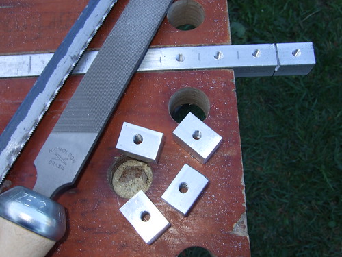
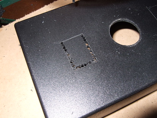
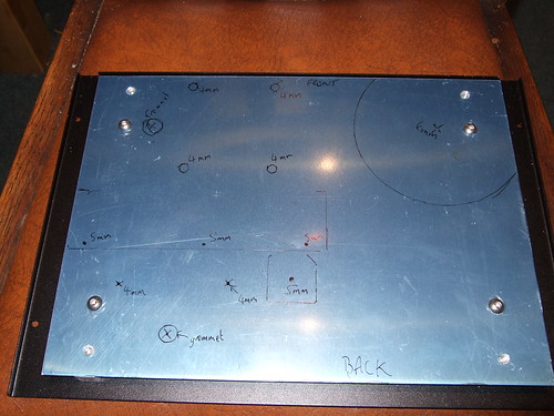
Once I was happy, I marked up the false bottom for drilling.

3792792523_c35326f591.jpg

Marked up false bottom.

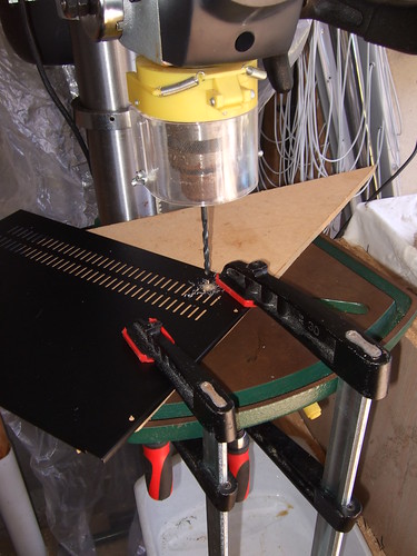
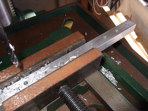
The drilling, deburring and tapping of holes actually took some time. I clamped the two false bottoms together, to arrive at a matching pair. So, once the drilling. deburring and tapping was finished, I thought I have a trial build.

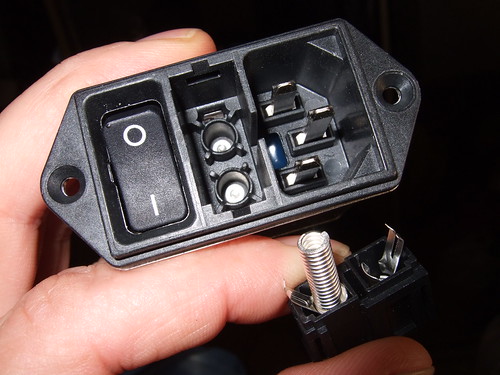
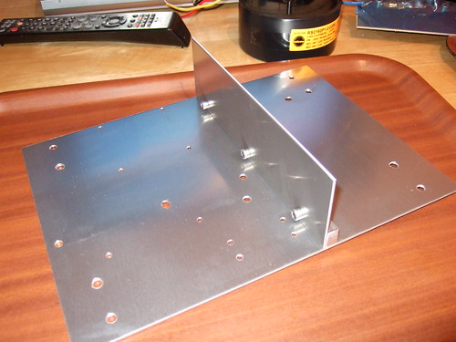
Firstly, I bolted a chassis divider to a length of aluminium bar, which I then bolted to the case. This provides additional shielding for the more sensitive audio components from the power inlet and transformer.

3792796695_431d24e32c.jpg

Internal chassis divider.

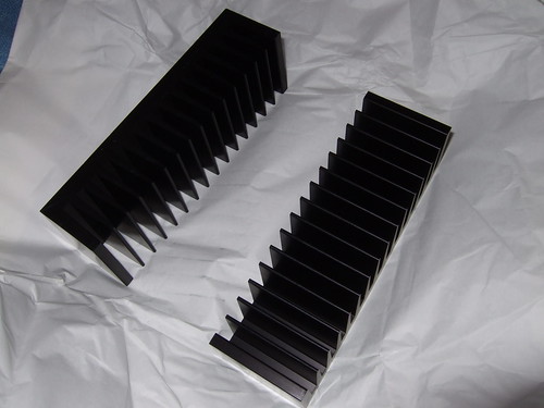
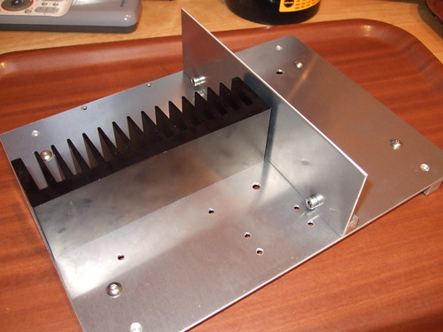
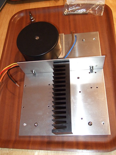
The next to go in was the heatsink. This has been drilled and blind threads tapped into it from underneath, allowing the heatsink to be bolted to the false bottom.

3792798105_ed2fff57ef.jpg

Heatsink in place.

I put the transformer in next. This sits on top of a little mounting plate of 5mm thick aluminium, which allowed the wires to remain untrapped by it's own encapsulating case. A single bolt goes through the middle of the transformer, mounting plate and false bottom.

3793613896_6ce6bf0ba9.jpg

Transformer in place.

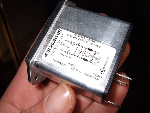
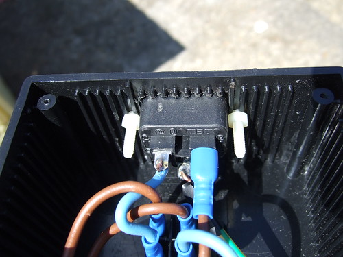
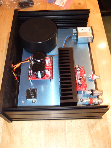
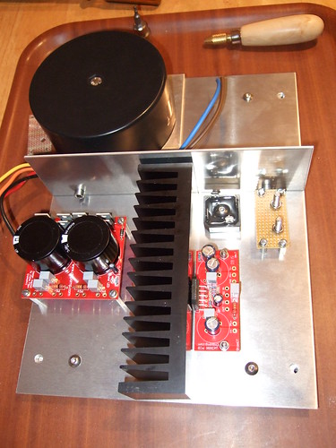
And finally, I fixed the PCBs and disconnecting network (more on this later) onto the false bottom. Clearly, it still needs to be wired together and there's one or two additional components which may yet be required (soft start circuit, DC blocking caps and high and low pass filters, etc), but essentially, the core elements are in place.

3792801041_c268aca7d8.jpg

All major components in place
 

PJPro

New member
Jan 21, 2008
274
0
0
Visit site
It's been some time since I provided an update and, to be honest, contribute to this forum at all. Why? I've been really busy trying to finalise the design of these amps. It's proved to be much more complex (and therefore expensive) than I thought. It's probably fair to say that my natural inclination to want to get things as near to prefect as possible hasn't helped. That's engineers for you!

So where am I? See the picture below.

3821324618_9f790b9611.jpg

Mono amplifier component layout and wiring.

I'll do a series of posts to cover each of the components in turn and try to explain what they contribute to the amplifier as a whole.
 

PJPro

New member
Jan 21, 2008
274
0
0
Visit site
Power inlet module

The unit comprises of an IEC plug, fuse and switch. I've already posted a picture of this but I'll include one here for your convenience.

3772264039_f8308cbf9d.jpg

Power inlet module

The IEC plug provides a way of getting power into the case using an (incorrectly named) kettle lead.

The unit allows the use of dual fuses. As mentioned previously, in the UK only the live should be fused. Therefore, I have ordered a fuse drawer complete with shorting bar (the spring thingy). If a short occurs in the amp, you want the fuse in this drawer to blow.

You can work out the rating of the fuse using

I = VA / V

where I is the current (amps), VA is the Volts Amps rating of the primary transformer and V is the mains voltage.

So, for my amp, VA = 160 and V = 240. Therefore I = 160 / 240 = 0.67A. The transformer should never draw more than this when working to it's maximum rating.

I've actually gone for a slow blow fuse rated a little higher at 0.8A. A slow blow fuse is necessary due to the sudden inrush of current when the amp is switched on. The transformer needs this current to get it's magnetic field going (so it'll actually do some transforming) and the large capacitors on the power supply add to this as they build up charge. Indeed, the sudden inrush of current will be sufficient to keep blowing the fuse everytime you switch on the amp. To get around this you can do a couple of things. You can up the rating for the fuse or you can add a soft start circuit.

If you up the rating of the fuse you risk high levels of heating within the case, should something go wrong. So, a 2A fuse will pass 4A for many seconds or minutes resulting in heating of up to 1kW until it blows (so I've been informed). This is bad. Very bad. So, I've gone for the soft start. I'll cover how this works in a future post.

The DPST (dual throw, single pole) switch acts as the main switch and cuts off all power to the case.

swdpst.gif

DPST Switch

The unit includes RF filtering circuitry. This prevents RF entering the case. Clearly, given it's size, it isn't going to compete with an Isotek substation. However, a clean(er) power supply won't hurt.

The unit is made by Schurter.
 

PJPro

New member
Jan 21, 2008
274
0
0
Visit site
Safety Earth (SE)

The most important part of the entire amp. This prevents someone getting electrocuted by providing a path to earth for any shorts making contact with the case (rather than you or somebody else) and blowing the fuse in the power inlet module in the process.

My safety earth will be a stainless steel bolt, toothed washer, and nut which will mechanically fix the earth wire from the power inlet module to the case. It will service no other cable.

I'll also make sure that the wire is sufficiently long so that it is the last wire to come detached from the power inlet module should someone try to take the back off the case.

Safety is my prime concern with these amps and I am keen to ensure I get this aspect of the build correct.
 

PJPro

New member
Jan 21, 2008
274
0
0
Visit site
Soft Start Circuit
This circuit's only job is to help limit the inrush of current when the amp is turned on thereby allowing the correct rated fuse to be used. It also prevents that thump through your speakers when you turn on the amp.

The circuit has it's own dedicated auxilllary power supply which is a 5VA, 9V toroidal tranformer. The basic circuit comprises of a bank of resistors, a relay and a relay control circuit.

p39-fig1.gif

Soft Start Resistors and Relay Contacts

Refering to the above picture, the mains live comes in at A. When the amp is switched on and while the relay is open, the primary transformer (located beyond SA) has to draw in the current it needs through the bank of resistors (R1, R2 & R3). The resistors, not surprisingly, resist the passage of this current....effecting the soft start. Once the relay (basically an electronically controlled switch) is closed, it shorts out the resistors, allowing the current to bypass the resistors...allowing full mains power to the primary transformer.

So, the key to soft starting is closing the relay at the correct moment....eg after the transformer has been given sufficient time to generate the required magnetic flux and the smoothing capacitors have been allowed to charge.

Well, the closing of the relay is achieved through knowledge of capacitor charging times and the impact of resistors on that charging time, which causes changes in circuit voltages to activate transistors which ultimately activate the relay i.e close it.

Alternatively, you can buy a PCB with instructions. I've gone for this one by Rod Elliot of ESP. As far as I can tell, Rod is well respected and his products (including this circuit) have been successfully used for some time within the DIY community.

Unfortunately (for this thread), he is fairly protective of his designs and I am unable to show detailed pictures of his PCB or even a schematic of the full purchased design. However, I don't think that level of detail will really be missed here.

What I can say is that Rod's design requires a switch (additional to the one on the power inlet module) to be incorporated into the overall circuit. So, I could have gone for a simple 240v 10A rated DTSP switch on the front panel. But where would be the fun in that?

I'll cover the switch I selected in the next post.

Incidentally, if when you turn on your amp you hear a number of small clicks, it's probably the relays activating as part of the soft start mechanism of the amp....although solid state relays (no moving parts) are becoming more widespread.
 

TRENDING THREADS

Latest posts