On with the build....
This session involved assembly of the case. The case is in four parts, comprising of the back and front panels and the top and bottom panels. The top and bottom panels also form the sides. Also included in the case kit is the volume knob, an earth attachment and self adhesive rubber feet.
Everything is grounded to the case. So, to insure a good contact between the front and back panels and the sides and top, you have to penetrate the case coating so that when the screws are tightened a continuous circuit is formed.
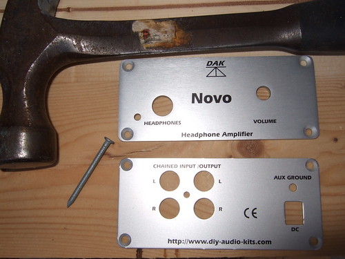
To do this, you "disturb" the countersinks which accept the screws. Graham recommends a small punch to do this. I used a suitably small nail and a hammer.
Front and back panels, galvanised nail and estwing hammer.
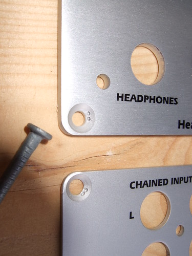
Using gentle taps with the hammer, I formed small indentations/ridges in the screw countersinks. I placed two of these in each countersink, ensuring they were positioned so that they would be covered up by the screw head.
The next step was to assemble the case grounding connection. This comprises of a bolt, some serrated washers, ordinary washers, a solder tag and a hex spacer. The instructions make the order of assembly clear. You just need to make sure the serrated washers are against the case, so that they bite into the surface when you tighten it up, ensuring a good connection to the case.
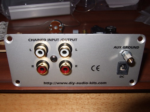
Once the case grounding connection is in place, you attach the back panel to the PCB. This attached to the phono block using a single screw.
The back panel fitted to the PCB.
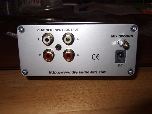
Note: the auxillary ground on the back panel is one end of the case grounding connection. The idea is that the auxillary ground allows the attachment of a earth wire if the user encounters any problems with mains hum.
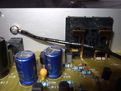
The grounding wires added in the previous session are soldered to the case grounding connection using the solder tag.
Grounding wires attached to back panel.
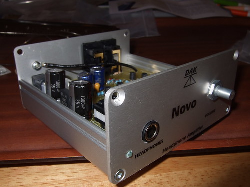
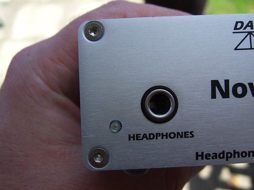
The bottom panel is slid onto the PCB, followed by the front panel. Ease the front panel on to ensure that you don't damage the LED. If you've made a bad job of fitting the LED, now is the time you'll find out. I followed the instructions and didn't encounter any problems. Use the supplied screws to secure the front and back panels to the bottom panel. Put the washer and nut on the volume pot spindle.
Back, front and bottom panel enclosing the PCB.
I kept the screws and nut on the spindle fairly loose at this stage, to allow me to wiggle things around and get the top to fit. So, placing the top on, fit the screws and tighten everything up. Fit the volume knob. Stick on the rubber feet.
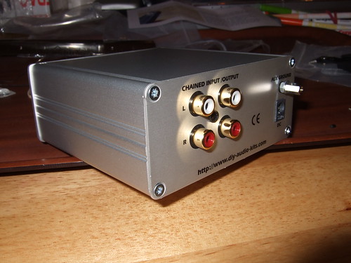
Completed Novo from the back, right.
Completed Novo from the back.
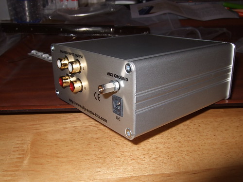
Completed Novo from the back, left.
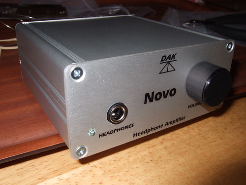
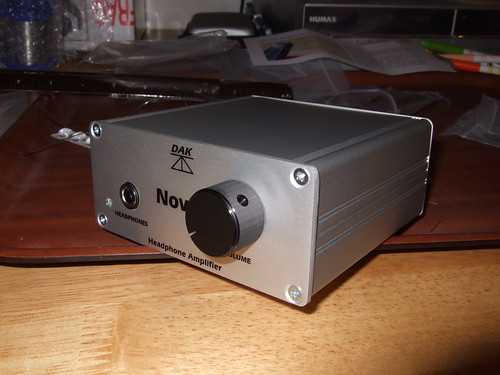
Completed Novo from the front, left.
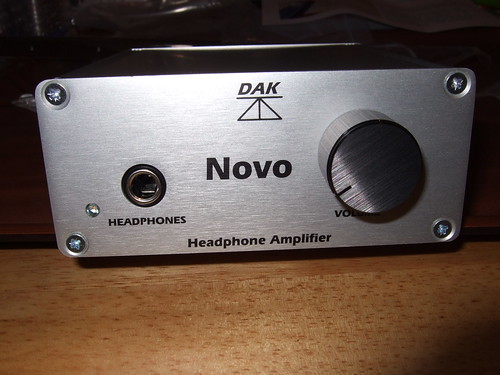
Completed Novo from the front.
Completed Novo from the front, right.
Waaaaahhhhaayyyy! AJPro celebrates completion of the build!
All that remained was to construct the power supply (very very simple, clip together design) and everything was done and ready for a listen....or was it? Not quite.....
This session took around 30 minutes.
In the next session I cover testing the build. Oho.

