DIY Headphone Amp #2 - Graham Slee Novo

PJPro

New member
Jan 21, 2008
274
0
0
Visit site
I've recently developed an itch to get a new headphone amplifier. I get it every 6 weeks or so. I would have liked to get the Stello HP100. However, recent price rises have put it out of my league.

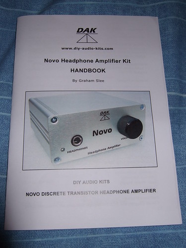
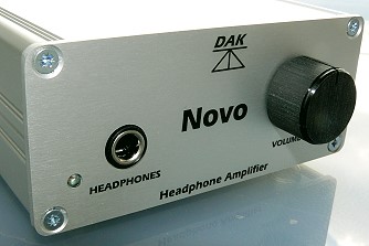
So, given my recent success with my first diy headphone amplifier (see here), I thought I'd have a go at building the recently available Novo kit from Graham Slee. The kit uses exactly the same components as the factory made Novo. The only difference is the front panel graphics. WHFSV rate the Novo as a 5 star product.
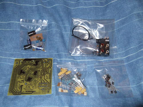
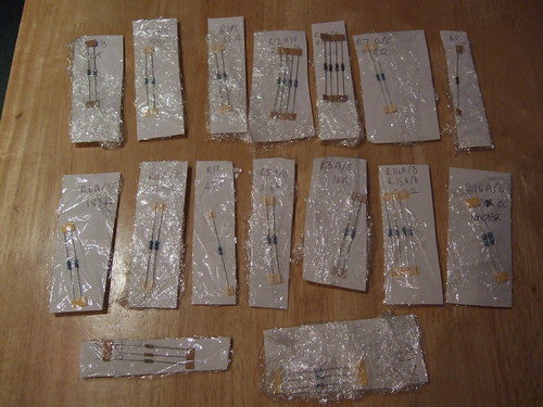
novo-kit-close-up.jpg

The Novo Kit

Costs
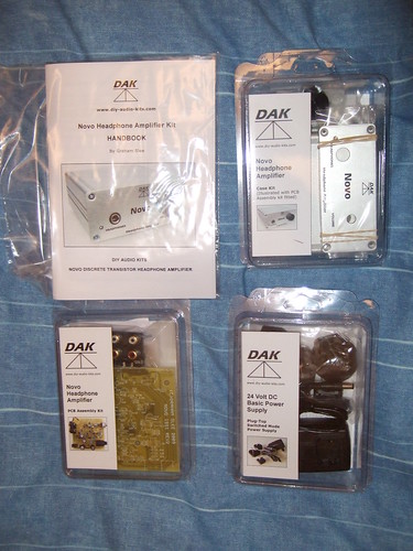
I went for the complete kit costing £120 + VAT + Shipping. For me in the UK, this translates into a total cost of £147.77. The complete kit comprises of a PCB kit (with components), a Power Supply kit and an Case kit. This compares to the ready made Novo cost of £200 + VAT. So, the cost of making the amplifier is approximately £80.

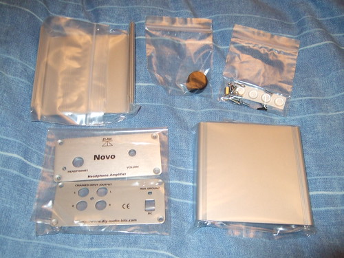
You are able to buy the PCB kit on its own for £76 + VAT + Shipping or the PCB and Case Kit (ie no power supply) for £112 + VAT + Shipping. So, the power supply costs around £8 + VAT and the case £36 + VAT.

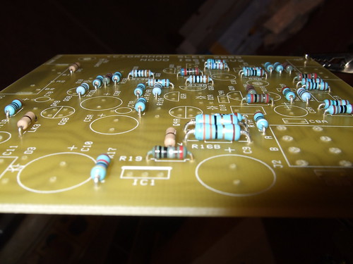
It's quite interesting to do this breakdown of costs.....something you aren't ordinarily able to do with commercially available kit. The stuff that does the business (PCB + components) is under half the cost of the completed factory built amp. Factor in the bulk of the labour, say £60, and the total for the things that actually makes the sound is approx £130 or 65% of the total expenditure. Make of this what you will.

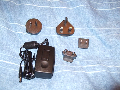
My only other observation is that the power supply seems a little on the cheap side. I don't know if Graham does a more expensive version. If it were my business, I'd offer a power supply kit in a similar case to the amp....although I understand that power supplies tend to be more dangerous for the amateur to build because you are dealing with 240V rather than the usual 12V.

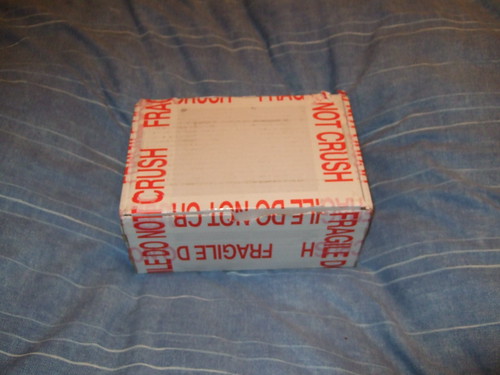
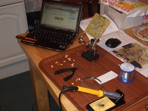
Anyway, the kit was ordered on Sunday night and arrived today (Wednesday).

MMMmmmm. April the first.
 

Andrew Everard

New member
May 30, 2007
1,878
2
0
Visit site
It's not uncommon for the casework, screen printing and so on to account for a significant amount of the cost of a product like this. In fact more than one manufacturer has told me in the past that the case and fascia of a product contributes a lot more to the cost than the bits that make the noise.

The rest? Well, of course you're not taking a dealer margin, which on a product like this from a small manufacturer could easily contribute the difference between kit and retail product. I'd suggest the manufacturer is still making a sensible margin...
 

PJPro

New member
Jan 21, 2008
274
0
0
Visit site
I've taken a few pictures of the kit and will provide a few first impressions.

The kit is delivered in a well wrapped/sealed box
3404475581_544a86dd06.jpg


The box contains the three kits plus an instruction booklet. The booklet also contains a colour picture of the completed PCB and the schematic. The booklet states a cost of £15....although it's cost is included in the price of the kit.
3405288644_33fa097be3.jpg


The case kit contains the front and rear panels and top and bottom all in reassuringly thick aluminium. A metal knob is provided (much like the one I used for my CMoy) along with various bolts, nuts and rubber feet. The panel graphics are well done. Nice. I can see why it cost £36 + VAT.
3405292532_a1096dde22.jpg


The power supply kit is fairly small and provides a variety of plug attachments.....presumably to support sales to different countries. It feels lightweight and is made out of cheap feeling plastic. Not good. I now understand why it costs £8 + VAT.
3405294428_2102773c15.jpg


The PCB and components kits contains the PCB (not surprisingly), capacitors, resistors, semiconductors (for the power supply circuit....remember this is a discrete amplifier so no opamps here) and miscellaneous bits and pieces e.g DC jack, phono jacks, a volume pot, an LED, etc. There doesn't appear to be an on/off switch and the volume pot doesn't provide on/off capability either.
3404489373_8964d1d875.jpg


I've not looked at the components in too much detail, but the capacitors look like the same make as I used in my CMoy e.g. Nichicon. Slightly disappointed that the volume pot isn't Alps.....as far as I can tell it's unbranded.

I was expecting the resistors, capacitors, etc to be bagged up and identified separately. This is not the case. A guide is supplied in the handbook which relates to the strips on the resistors, for instance, and this has me more than a little worried. It's gonna be easy for a numpty like me to make a mistake and not realise until it's too late. I'll report back on ease of identifying components as I go. Perhaps it's not an issue.

In the problems section of the handbook it states that electronics grade cored solder needs to be used not DIY formulations. It would have been nice if some of this solder had been provided with the kit. I have my silver solder but didn't really want to use that due to the extra heat required to melt it.

The PCB artwork (the metal stuff underneath) and the screen printing (the marking on top of the board which shows where to fit the components) looks good and is clear.

I was going to post a photo of the PCB here but am slightly concerned that this may reveal slightly more than Graham would appreciate. I'll contact Graham and inform him of this thread. If he's happy, I'll post the picture.
 

PJPro

New member
Jan 21, 2008
274
0
0
Visit site
Andrew Everard:
The rest? Well, of course you're not taking a dealer margin, which on a product like this from a small manufacturer could easily contribute the difference between kit and retail product. I'd suggest the manufacturer is still making a sensible margin...

OK. Accepted. However, the amp can be purchased direct from the manufacturer for £200 + VAT.

I wasn't really trying to make a comment on margin (because I'm assuming the kit contains margin as well), just trying to demonstrate how the money is divided up between the components, the case and the construction labour.

Having had a quick look at the kit, I suspect this is going to be a pretty fearsome build for me and £80 for construction is going to look cheap. Still, I'm up for it. And if I end up with nothing, I'll take in on the chin like a man......just don't tell my wife!
 

PJPro

New member
Jan 21, 2008
274
0
0
Visit site
Andrew - I'm going to copy you in on my email to Graham using the whathifi@haymarket.com email address just so you know first hand any concerns Graham may have.
 
A

Anonymous

Guest
PJPro writes: The power supply kit is fairly small and provides a variety of plug attachments.....presumably to support sales to different countries. It feels lightweight and is made out of cheap feeling plastic. Not good. I now understand why it costs £8 + VAT.

Quick to judge? "Not good"? The Novo that scooped group test winner in What Hi-Fi April 09... sounding "involving" and "addictive" used the exact same power supply.

PJPro writes:...the capacitors look like the same make as I used in my CMoy e.g. Nichicon. Slightly disappointed that the volume pot isn't Alps.....as far as I can tell it's unbranded

The volume pot IS ALPS - it is stamped into the metal shield. It is sourced through an Alps official distributor having ISO9000 such that the part can be traced all the way back to Alps.

One of the capacitors is a Nichicon type "Fine Gold"

PJPro writes: I was expecting the resistors, capacitors, etc to be bagged up and identified separately. This is not the case. A guide is supplied in the handbook which relates to the strips on the resistors, for instance, and this has me more than a little worried. It's gonna be easy for a numpty like me to make a mistake and not realise until it's too late.

Unfortunately because of the speed the webpage at diy-audio-kits.com was put online we forgot the following statement "For electronics hobbyists having good soldering skills and a general good understanding of electronic components", but it is now online. It does however say this on the packing the kit is supplied in. We can offer a refund if you feel you have been misled.

PJPro writes: In the problems section of the handbook it states that electronics grade cored solder needs to be used not DIY formulations. It would have been nice if some of this solder had been provided with the kit.

We have also added to the website "Solder not included..."

And stated the reason why...

"Amateur constructors often prefer to use Tin/Lead solder but under EU RoHS legislation we are not allowed to include it in any product and that means kits too. Lead-free solder can be very difficult for the hobbyist and therefore the solder is left out of our kits"

PJPro writes: I was going to post a photo of the PCB here but am slightly concerned that this may reveal slightly more than Graham would appreciate. I'll contact Graham and inform him of this thread. If he's happy, I'll post the picture.

Please follow the gudelines in our handbook...

"Our excellent value for money designs take many months (sometimes years) of serious development. Please help us to be able to continue to design great circuits by preventing others copying the kit you have just bought. You can also support us by telling us if you discover anybody breaching our copyright so we can at least prevent them obtaining any other of our designs - please let us know"

Looking forward to seeing how it goes.

Best wishes,

Graham
 

PJPro

New member
Jan 21, 2008
274
0
0
Visit site
Graham Slee:
PJPro writes: The power supply kit is fairly small and provides a variety of plug attachments.....presumably to support sales to different countries. It feels lightweight and is made out of cheap feeling plastic. Not good. I now understand why it costs £8 + VAT.

Quick to judge? "Not good"? The Novo that scooped group test winner in What Hi-Fi April 09... sounding "involving" and "addictive" used the exact same power supply.

Not a comment on its effect on sound quality, more aesthetics. It might perform but I stand by my comments. It feels and looks cheap....which it is at £8.

Graham Slee:
PJPro writes:...the capacitors look like the same make as I used in my CMoy e.g. Nichicon. Slightly disappointed that the volume pot isn't Alps.....as far as I can tell it's unbranded

The volume pot IS ALPS - it is stamped into the metal shield. It is sourced through an Alps official distributor having ISO9000 such that the part can be traced all the way back to Alps.

One of the capacitors is a Nichicon type "Fine Gold"

I'll double check. Apologies if I got this wrong and thanks for the correction.

Graham Slee:

PJPro writes: I was expecting the resistors, capacitors, etc to be bagged up and identified separately. This is not the case. A guide is supplied in the handbook which relates to the strips on the resistors, for instance, and this has me more than a little worried. It's gonna be easy for a numpty like me to make a mistake and not realise until it's too late.

Unfortunately because of the speed the webpage at diy-audio-kits.com was put online we forgot the following statement "For electronics hobbyists having good soldering skills and a general good understanding of electronic components", but it is now online. It does however say this on the packing the kit is supplied in. We can offer a refund if you feel you have been misled.

Thanks for the offer. But I'll take my chances. I think updating the website will avoid future misunderstanding, so a worthwhile addition.

Graham Slee:

PJPro writes: In the problems section of the handbook it states that electronics grade cored solder needs to be used not DIY formulations. It would have been nice if some of this solder had been provided with the kit.

We have also added to the website "Solder not included..."

And stated the reason why...

"Amateur constructors often prefer to use Tin/Lead solder but under EU RoHS legislation we are not allowed to include it in any product and that means kits too. Lead-free solder can be very difficult for the hobbyist and therefore the solder is left out of our kits"

Yes. Fully understand the reasoning. Have bought some 63/37 from RSComponents for the princely sum of £27 delivered.

Graham Slee:

PJPro writes: I was going to post a photo of the PCB here but am slightly concerned that this may reveal slightly more than Graham would appreciate. I'll contact Graham and inform him of this thread. If he's happy, I'll post the picture.

Please follow the gudelines in our handbook...

"Our excellent value for money designs take many months (sometimes years) of serious development. Please help us to be able to continue to design great circuits by preventing others copying the kit you have just bought. You can also support us by telling us if you discover anybody breaching our copyright so we can at least prevent them obtaining any other of our designs - please let us know"

If you think I stray outside of your guidelines, please email me and I will remove the offending picture.
Graham Slee:

Looking forward to seeing how it goes.

Best wishes,

Graham

Graham, it's really cool to have another manufacturer posting on the website. Thanks for replying to my email and posting on my thread.
 

JoelSim

New member
Aug 24, 2007
767
1
0
Visit site
Good luck mate. My Gram Amp was well packaged too and it took me ages to do. I had to plug the power lead in and all sorts...
 

PJPro

New member
Jan 21, 2008
274
0
0
Visit site
Cheers JoelSim. Having looked at the bits, I've got a nasty feeling I'm gonna make a mess of it. Still, I'll give it my best shot.
 
A

Anonymous

Guest
PJPro:Cheers JoelSim. Having looked at the bits, I've got a nasty feeling I'm gonna make a mess of it. Still, I'll give it my best shot.

Nah, you'll be fine. Just take it slow and double check everything before commiting with the solder. Look forward to seeing the finished product.
 

PJPro

New member
Jan 21, 2008
274
0
0
Visit site
I can confirm the pot is indeed made by ALPS and, as Graham said, this is stamped onto the side of the casing (easy to over look)......I am familiar with the "Blue Velvet" variety, as used on my first amp, so was looking for something similiar. The boutique version is the Black Velvet.
 

PJPro

New member
Jan 21, 2008
274
0
0
Visit site
Finally got the solder today.....it's a long story which I won't bore you with.

3425263130_caf25a3f83.jpg


It's 63% Tin and 37 % Lead as recommended by Tangent here.

The solder was purchased from RS Components. You can find it here.
 

PJPro

New member
Jan 21, 2008
274
0
0
Visit site
idc:Any progress with the soldering?
Yep. It's finished! I'm listening to it now. I'll be updating the post over the next few days to record the build, complete with pictures.

There may actually be a bit of an issue. My testing, with a multimeter, indicates that certains voltages are outside of the values suggested by Graham. However, I've checked, checked and checked again that the components are correctly positioned and ensured that nothing is getting hot. This post build testing is on top of my check, check again and check again during the build.

I'm pretty confident the build is good....so I am uncertain if I have an issue or not. I'll email Graham tomorrow. Watch this space!
 

PJPro

New member
Jan 21, 2008
274
0
0
Visit site
So, on with the build documentation.....

Firstly a word about the previously mentioned Handbook. Clearly, the whole kit is going to sink or swim based on the quality of the handbook.

3452896281_32b75537d8.jpg

The Handbook

The good news is it's pretty good. There are one or two issues for the less capable builder (such as myself) which I'll come to later. However, for the more capable builder, it provides everything you need and more. I hope that during this thread I can clarify these issues, provide solutions and take some of the "fear" out of the kit.

So what does the handbook contain? Well, it provides a list of the components required to make the amp, a table to interpret the resistor colour codes, a detailed breakdown of how the amp works, assembly instructions for the PCB, Case and Power Supply kits, testing guidance and fold out extra large pictures; one colour photo of a completed PCB and one schematic. Phheeeww! There's also some other stuff in there detailing the spec of the amp, warranty and limitations.

The resistor colour code table assumes some previous experience/knowledge. An example of interpreting colour bands is given but doesn't really explain too much eg which end of the bands to start trying to read the colours (ie which band represents the tolerance of the resistor) and when to switch from digits to zeros. I'm sure an experienced builder would scoff but, certainly, I did't know the answers to these questions.

3453712850_27c58d48ee.jpg

The Resistor Colour Code Table

The How it Works section covers three pages and gets right into the detail. I did skim read this section and will return to it. But it is not for the beginner. Fortunately, no understanding of how the amp works is required to complete the build!

The Assembly Instructions on first reading seem a bit vague. The text is interspersed with photos. Graham does provide little tips and points to look out for as you go. The instructions cover 6 pages and are used in conjunction with the large fold out colour photo of a completed PCB.

3452900803_25aa934871.jpg

A page from the assembly instructions

3453717178_e60ca323c0.jpg

Another page from the assembly instructions

The Testing section covers a page and is used in conjunction with the large fold out schematic. There's even tips on settings for an oscilloscope should the need arise.

It took me about 1/2hr or so to flick through the handbook and I was itching to get started.
 

idc

Well-known member
An engineer friend told me yesterday about the problem of 'tin whiskers' in solder as the lead content is reduced to make it more 'environmentally friendly'. Is there possibly a quality issue with the solder you have to use?
 

PJPro

New member
Jan 21, 2008
274
0
0
Visit site
The reason that the kit doesn't come with solder is that most DIYers (as far as I can tell) prefer to use a lead based solder rather than the lead free stuff that manufacturers are required to use/supply with their products. However, you can still buy solder containing lead.

The reason I went for the 63% tin 37% lead is that it is supposed to be of higher quality and easier to work with than the standard 60/40 solder.

I haven't experienced any tin whiskers as far as I know......but that's not to say that your friend isn't correct.
 

PJPro

New member
Jan 21, 2008
274
0
0
Visit site
Continuing with the build.....

The first step was to identify the resistors. As stated above, the manual provides a table to help decypher the meaning of the colour bands. I was a bit worried about this as misidentifying a resistor would have severe implications once soldered onto the PCB. In total there are 16 different resistors in the kit.

The resistors were in groups according to type i.e. all the 20 kilo Omhs. So to a certain extent, it was possible to eliminate certain resistance values simply based on how many resistors were within a particular group. However, this only gets you so far. You have to suss out the colour coding.

First problem. Which way around to you read the colours i.e. which is left and which is right? In this kit you only get red and brown bands on the right. These rightmost bands, I believe, give an indication of the tolerance of the resistor. This simply means how far they may be from their stated resistance value e.g. 1% or 5%. I also found that the rightmost bands tend to be wider, with a greater distance to it's neighbour than the other bands on the resistor.

Having learnt how to orientate the resistor, it was now just a simple task of using the colour table to establish the resistance. Hhhmmm. This proved to be a little tricky. I think the way it works is, starting from the leftmost band, use the digit column for the colour bands until a black band is encountered and then switch to the number of zeros column. The tolerance column is used for the rightmost band.

I went through each resistor group in turn working out the resistance using the colours and then testing with a multimeter. I also used an excellent online tool....I'm sooo glad I bought that Samsung NC10, cos I could use it on my work bench (kitchen table). The tool can be found here and allows input for 4, 5 and 6 band resistors.

3452954805_f99e05c8b5.jpg

Identifying the resistors

I needed a magnifying glass for this and some of the colours were easy to confuse. If I was in doubt, I'd put the resistor to one side and come back to it. Through a process of elimination, measurement, colour coding and best judgement I managed to identify the lot.

3452945467_b7f9ac816c.jpg

Resistors identified

Once all the resistors were identified, I packed them up and put them away for another day.

3453766998_aff90606a5.jpg

Resistors packed away for another day.

Time taken - 1hr

I have to say that Graham could have made this a lot easier simply by providing the colours for the resistors. This would have dramatically derisked the project for me and the budding DIYer.

So, I'll provide the colours here for the benefit of others who follow. I'll also provide pictures from the WhatCircuits site of the resistors.
 

PJPro

New member
Jan 21, 2008
274
0
0
Visit site
Here are the pictures, followed by a text representation for each resistor type in the kit.

The tolerance colour follows |T| in the text and is identified by the green arrow in the pictures.

The text also provides the number of resistors of that type in the kit as a prefix to the value.

No picture for this one. A single black band.
3 x 0 Ohms Black

3459820531_3bdb5d9ac6.jpg

1 x 1 Ohms Brown | Black | Brown | Silver | Brown |T| Red

3459819557_be91eb339a.jpg

4 x 3.3 Ohms Orange | Orange | Black | Silver |T| Brown

3459817903_b17ca20deb.jpg

3 x 10 Ohms Brown | Black | Black | Gold |T| Brown

3459820137_44c066baff.jpg

2 x 33 Ohms Orange | Orange | Black | Gold |T| Brown

3459815855_7896ee5e34.jpg

2 x 56 Ohms Green | Blue | Black | Gold |T| Brown

3459818483_c8f6a48459.jpg

2 x 120 Ohms Brown | Red | Black | Black |T| Brown

3459816949_c109420869.jpg

2 x 180 Ohms Brown | Gray | Black | Black |T| Brown

3460634028_2ec6eec38c.jpg

2 x 910 Ohms White | Brown | Black | Black |T| Brown

3459819075_c7f47ffb10.jpg

4 x 1 kilo Ohms Blue | Black | Black | Brown |T| Brown

3459816797_c86aeb85c2.jpg

2 x 1.6 kilo Ohms Brown | Blue | Black | Brown |T| Brown

3460634344_8e0df14582.jpg

2 x 6.2 kilo Ohms Blue | Red | Black | Brown | Brown |T| Red

3459816243_c016b75d4f.jpg

2 x 16 kilo Ohms Brown | Blue | Black | Red |T| Brown

3460632390_9a87969a15.jpg

4 x 20 kilo Ohms Red | Black | Black | Red | Brown |T| Red

3459815063_9295500e6c.jpg

1 x 47 kilo Ohms Yellow | Violet | Black | Red |T| Brown

3460633488_a453b60811.jpg

2 x 150 kilo Ohms Brown | Green| Black | Orange |T| Brown
 

PJPro

New member
Jan 21, 2008
274
0
0
Visit site
Now that the resistors have been identified, it's time to start soldering.

Before you start, I'd recommend that you take a photo of the PCB artwork e.g. the tracks and pads on the underside of the board. This will provide a valuable resource when you come to check the board once you've completed your build. You'll be able to compare the unsoldered board to a photograph of the soldered board using something like Windows Photo Gallery. This is great. You can listen to music while you examine the board for bridged tracks, poor joints, etc without the hassle of magnifying glasses, poor light etc.

The manual doesn't give too much information on what goes where. But, then again, it doesn't really need to. The strategy is to solder on the low level, small, close to the board stuff, and build up in layers to the big stuff.

So, you start with the resistors. Simply select the resistor you want to solder onto the board, and find it's marked location on the PCB. I'd recommend a final check of the bands before soldering the resistor on and double check the fold out picture of the completed board at the back of the manual.

Once you're happy you have correctly identified the resistor and it's location of the board, it's a simple matter of bending over it's leads and inserting it onto the board. Make sure that you orientate the colour bands in the same direction as the PCB legend. This makes it easier to check the board later.

3452928329_a9f17971df.jpg

Final checking of the resistors as I solder them onto the board.

Next comes the actual soldering. I use "Helping Hands" (£10 from Maplins) to hold the board so that I have both hands free. I firstly tin the soldering iron (melt some solder onto the iron tip so that it is covered) and wipe off the surplus onto a wet sponge. It's then a matter of applying the tip of the iron to the resistor lead and board pad for perhaps a second or so, to let them heat up, and then apply the solder to the lead/pad/iron tip.

It's worth trying not to put too much solder on but enough to hold the resistor firmly in place. Repeat on the second lead and then snip off the surplus lead with side cutters.

To get all of the resistors in place took about 2 hours.

3453746986_3b92a1b11b.jpg


The soldering was actually really easy due to the wide spacing of the track and pads. Compared to the CMoy, the soldering was proving to be a real joy and totally absorbing. Even someone as inexperienced as I could make a decent job of it.
 

TRENDING THREADS

Latest posts