A
DIY Headphone Amp #2 - Graham Slee Novo
Page 2 - Seeking answers? Join the What HiFi community: the world's leading independent guide to buying and owning hi-fi and home entertainment products.
You are using an out of date browser. It may not display this or other websites correctly.
You should upgrade or use an alternative browser.
You should upgrade or use an alternative browser.
idc
Well-known member
- Jan 2, 2008
- 1,172
- 147
- 19,370


'For a moment I thought I was the only one reading this thread!' far from it. A few questions if you do not mind.
I am going to really thick here and I ask because the picture of the board side on looks so neat, which side do you solder? Do you push the leads through and solder from below or from above as the lead goes through?
What happens if you make a mistake? Can you un-solder?
Thanks
I am going to really thick here and I ask because the picture of the board side on looks so neat, which side do you solder? Do you push the leads through and solder from below or from above as the lead goes through?
What happens if you make a mistake? Can you un-solder?
Thanks
First well done for having a go at hifi diy, when you get it right nothing else is more pleasing.
hi, just read all your chapters on building the head phone amp, quite entertaining.
i don't want to patrenise but the purchase of a good quality multi meter will pay for itself in no time, there is a vast range on the market, from the cheap and nasty to the lab (prohibative prices), but plenty in between, i favour Fluke unit,(may be because they are the choice unit with in my profession), then the need for resistor colour banding isn't such a problem.
As reguards solder i have always plumpt for Wonder solder, not cheap but well worth it, i use a varible heat control soldering station, available from rs.
Keep up the good work, photo's excellent,photgraphy my 2nd hobby,"man goes to work for his toys,eats and drinks when he can".
idc:
Which side do you solder? Do you push the leads through and solder from below or from above as the lead goes through?
The photo posted above shows the top of the board. The top has pictures and text on top which show you where to place the component. The component leads/pins are pushed through the board from the top and get soldered underneath onto the pads. The pads are linked by tracks and act essentially like wires to join the components up.
With the Helping Hands I use, you can place the component on the board and then turn the board over to solder the component in place. The components do tend to want to fall out at this point and, depending on the component you are trying to solder, there are different things you can do to prevent this.
If you are soldering resistors, diodes or bipolar transistors, you can bend the leads out a little once they have been passed through the holes on the board. Bigger stuff you have to try and support with a finger......being careful not to burn yourself as the components can heat up very quickly.
idc:
What happens if you make a mistake? Can you un-solder?
Yes you can. But the difficulty involved depends on the number of leads/pins which have been soldered.
With a resistor, where there are only two leads, it isn't too much of a problem. Removing a volume pot, with it's many pins, is much more difficult.....although you're much less likely to solder the big stuff in the wrong place.
The other difficulty is damaging a component through too much heat when you try to remove it from the board. Examples of heat sensitive stuff will be transistors and certain capacitors.
The other difficulty is ending up with holes blocked with solder in the board so you can't place the replacement component on the board. This isn't an insurmountable problem.....but if you're not careful you can end up damaging the board....and that's a disaster!
The best strategy is to make absolutely sure that you get things in the right place first time. Double check and check again before soldering a component onto the board. This avoids a lot of agro later.
nomismo:
First well done for having a go at hifi diy, when you get it right nothing else is more pleasing.
Agree.
nomismo:
I've just read all your chapters on building the head phone amp, quite entertaining.
Only quite? I'll have to try harder!
nomismo:
i don't want to patrenise but the purchase of a good quality multi meter will pay for itself in no time, there is a vast range on the market, from the cheap and nasty to the lab (prohibative prices), but plenty in between, i favour Fluke unit,(may be because they are the choice unit with in my profession), then the need for resistor colour banding isn't such a problem.
Yes. Agree. We use Fluke at work. I'd like to get one of these.....but they cost about £230. That's a lot for the occasional use I'd get out of it.

Fluke 175
nomismo:
As reguards solder i have always plumpt for Wonder solder, not cheap but well worth it, i use a varible heat control soldering station, available from rs.
Wonder Solder? This? I've gone to great expense to get the stuff with lead...cos it's easier to work with. Surely this Wonder Solder is the same lead-free stuff you can get from Maplins isn't it?
First well done for having a go at hifi diy, when you get it right nothing else is more pleasing.
Agree.
nomismo:
I've just read all your chapters on building the head phone amp, quite entertaining.
Only quite? I'll have to try harder!
nomismo:
i don't want to patrenise but the purchase of a good quality multi meter will pay for itself in no time, there is a vast range on the market, from the cheap and nasty to the lab (prohibative prices), but plenty in between, i favour Fluke unit,(may be because they are the choice unit with in my profession), then the need for resistor colour banding isn't such a problem.
Yes. Agree. We use Fluke at work. I'd like to get one of these.....but they cost about £230. That's a lot for the occasional use I'd get out of it.
Fluke 175
nomismo:
As reguards solder i have always plumpt for Wonder solder, not cheap but well worth it, i use a varible heat control soldering station, available from rs.
Wonder Solder? This? I've gone to great expense to get the stuff with lead...cos it's easier to work with. Surely this Wonder Solder is the same lead-free stuff you can get from Maplins isn't it?
idc
Well-known member
- Jan 2, 2008
- 1,172
- 147
- 19,370
Thanks for the replies PJPro. I used to go to wrought iron night classes and made gates, a fireplace, security grills and all sorts. I really enjoyed it. Soldering and what you are doing is inspiring me to scale down what I did before and do what you are doing. But first I would need to learn and practice. Do you know of any starter kits with instructions for a wannabie solderer?
Maplins do a range of cheap kits you could try. I've not done any of them myself.
How about this one? It has an associated site here.

Super Stereo Ear Kit
Alternatively, you could try building a CMoy, as in my DIY Headphone Amplifier thread. But actually, the soldering onto the protoboard was far from easy. Indeed, this current kit is much easier to build.
How about this one? It has an associated site here.
Super Stereo Ear Kit
Alternatively, you could try building a CMoy, as in my DIY Headphone Amplifier thread. But actually, the soldering onto the protoboard was far from easy. Indeed, this current kit is much easier to build.
A
Anonymous
Guest
Nice build looking good, any chance you could take some close-up shots of the manual, would help me out alot, thanks bud
A
Anonymous
Guest
dean0:Nice build looking good, any chance you could take some close-up shots of the manual, would help me out alot, thanks bud
Yeah right. Try putting your hand in your pocket and buying the kit.
Yeah right. Try putting your hand in your pocket and buying the kit.
A
Anonymous
Guest
Nice looking build. It's making me think of giving it ago.
Given all your comments on here would you say that this might be an easier build tham the cmoy? It seems like this is better spaced out and what have you makeing access to every part easier?
I also like the fact that i can buy it ass a kit not having to buy everything from different sources.
Given all your comments on here would you say that this might be an easier build tham the cmoy? It seems like this is better spaced out and what have you makeing access to every part easier?
I also like the fact that i can buy it ass a kit not having to buy everything from different sources.
fast eddie:Nice looking build. It's making me think of giving it ago.
Given all your comments on here would you say that this might be an easier build tham the cmoy? It seems like this is better spaced out and what have you makeing access to every part easier?
I also like the fact that i can buy it ass a kit not having to buy everything from different sources.
Thanks Eddie.
This has been a easier build than the CMoy variant....but it costs a lot more. If you do go straight for the Novo kit, I'd recommend getting one of the cheap electronic kits from Maplins first to assess your soldering abilities and hone your skills.
In terms of getting the bits, the first DIY headphone amp provides the part numbers to enable you to buy just about everything from Mouser. Mouser now have an office in the UK. See this article. Would you believe they rang me up personally to tell me so...on the back of a single £100 purchase.
Incidentally, I did have a spare kit but I sold that a while ago now.
Once all the resistors had been applied, I moved onto the diodes.
There are only two types of diode used (excluding the LED), so they are easy to identify and find their location using the fold out picture of the completed PCB. Before soldering them into place you need to ensure that you get them on the board the right way round. Each diode has a band at one end and this needs to be be at the same end as the arrow point on the PCB legend.
Once the diodes were in place, I moved onto the smaller capacitors. There are 4 ceramic capacitors which are all the same, so easily identified. There are also a couple of tantalum beads. The only complication with these is that you need to get the positive lead in the positive hole and the negative lead into the negative hole on the board.
The positive lead on the tantalum bead is usually longer and there's a marking on the bead itself to indicate the positive lead. I've included a picture below of a bead supplied by Mouser. This particular bead is not found in the kit, but does show the markings and longer lead.

Tantalum Bead (not from kit - see text)
The transistors go in next. These are small black plastic things with three leads (see picture below). There are two types and they are easy to confuse. There are 8 PNP and 4 NPN. The difference between them, in terms of visible markings, is a single number. I used a magnifying glass and arranged them into groups before soldering, ensuring the number in each group was as expected. Before soldering, I double checked to make sure I had the right transistor which was going to into the right location in the board...you don't want to get this wrong!
The instructions recommend that the transitors leads are soldered into the board in a particular order i.e. Emitter, Base then Collector. This is because the Collector is less likely to be damaged by the heat from soldering. I didn't know which lead was which so simply did them in the order which was easiest and left maybe 10 seconds between each lead to let things cool down.
Graham has kindly clarified identification of the Emitter, Base and Collection. Here is a quote from Graham ....
"With the transistor laid flat on its face and the legs pointing toward you the connections are emitter - base - collector."
The next to go in were the middle sized capacitors. There are 3 polyester capacitors (grey) 2 polypropylene capacitors (blue). Again, easy to identify and solder onto the board. At this point I also soldered on four of the electrolytic capacitors: 2 gold, nichicon ones and two blues ones. Like the tantalum beads, the electrolytic capacitors need to be placed into the board being aware of polarity. The longer lead is positive. The negative lead is identified by a stripe on the body of the capacitor.
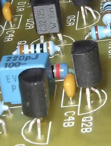
Picture showing three transisors (black things with 3 legs), 2 ceramic beads (beige blobs), a polypropylene capacitor (blue box) and a few resistors.
The next to go onto the board were the DC and headphone Jacks. These are a bit tricky as the pins are flat blades. This means the holes in the board are quite big. You need to fill the hole around the blades completely. I was a bit nervous about this bit....but I shouldn't have been.
I held the soldering iron onto the blade and pad for a few seconds longer than normal and ensured I had a good length of solder ready to apply to the tip. You just sort of keep applying the solder at a steady rate and it flows around the blade. See the picture below for the end result (this is actually the headphone socket).
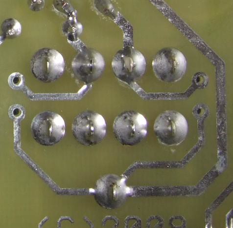
Soldered blades in large holes.
I then soldered in the two large, black electrolytic capacitors and the voltage regulator. Again, with the capacitors, you need to be aware of polarity. With the regulator, you need to ensure that the black plastic side is facing the outside of the board.
The final component to get applied during this session was the phono block. You have to ease a couple of clips through slits in the board and, again, solder the pins into the large holes in the board using the same approach as for the DC and headphone jack.
This session lasted 2 hours.
The reason I haven't provided many pictures along the way is I completely forgot all about documenting the build, so absorbing was the work. But I did take a few pictures at the end of the session.
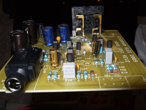
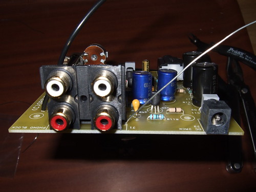
Almost complete PCB - front.
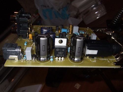
Almost complete PCB - left. You can see the DC jack on the left at the front. Behind it, you can see the phono block. In the middle are the two large electrolytic capacitors with the voltage regulator in between them. The headphone jack is on the right.
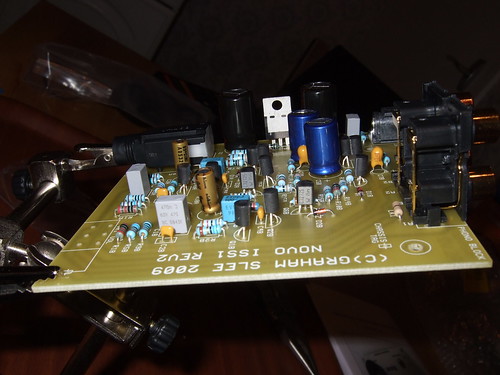
Almost complete PCB - right. On the left you can see the holes to accept the volume pot. That'll be covered in the next session.
There are only two types of diode used (excluding the LED), so they are easy to identify and find their location using the fold out picture of the completed PCB. Before soldering them into place you need to ensure that you get them on the board the right way round. Each diode has a band at one end and this needs to be be at the same end as the arrow point on the PCB legend.
Once the diodes were in place, I moved onto the smaller capacitors. There are 4 ceramic capacitors which are all the same, so easily identified. There are also a couple of tantalum beads. The only complication with these is that you need to get the positive lead in the positive hole and the negative lead into the negative hole on the board.
The positive lead on the tantalum bead is usually longer and there's a marking on the bead itself to indicate the positive lead. I've included a picture below of a bead supplied by Mouser. This particular bead is not found in the kit, but does show the markings and longer lead.
Tantalum Bead (not from kit - see text)
The transistors go in next. These are small black plastic things with three leads (see picture below). There are two types and they are easy to confuse. There are 8 PNP and 4 NPN. The difference between them, in terms of visible markings, is a single number. I used a magnifying glass and arranged them into groups before soldering, ensuring the number in each group was as expected. Before soldering, I double checked to make sure I had the right transistor which was going to into the right location in the board...you don't want to get this wrong!
The instructions recommend that the transitors leads are soldered into the board in a particular order i.e. Emitter, Base then Collector. This is because the Collector is less likely to be damaged by the heat from soldering. I didn't know which lead was which so simply did them in the order which was easiest and left maybe 10 seconds between each lead to let things cool down.
Graham has kindly clarified identification of the Emitter, Base and Collection. Here is a quote from Graham ....
"With the transistor laid flat on its face and the legs pointing toward you the connections are emitter - base - collector."
The next to go in were the middle sized capacitors. There are 3 polyester capacitors (grey) 2 polypropylene capacitors (blue). Again, easy to identify and solder onto the board. At this point I also soldered on four of the electrolytic capacitors: 2 gold, nichicon ones and two blues ones. Like the tantalum beads, the electrolytic capacitors need to be placed into the board being aware of polarity. The longer lead is positive. The negative lead is identified by a stripe on the body of the capacitor.
Picture showing three transisors (black things with 3 legs), 2 ceramic beads (beige blobs), a polypropylene capacitor (blue box) and a few resistors.
The next to go onto the board were the DC and headphone Jacks. These are a bit tricky as the pins are flat blades. This means the holes in the board are quite big. You need to fill the hole around the blades completely. I was a bit nervous about this bit....but I shouldn't have been.
I held the soldering iron onto the blade and pad for a few seconds longer than normal and ensured I had a good length of solder ready to apply to the tip. You just sort of keep applying the solder at a steady rate and it flows around the blade. See the picture below for the end result (this is actually the headphone socket).
Soldered blades in large holes.
I then soldered in the two large, black electrolytic capacitors and the voltage regulator. Again, with the capacitors, you need to be aware of polarity. With the regulator, you need to ensure that the black plastic side is facing the outside of the board.
The final component to get applied during this session was the phono block. You have to ease a couple of clips through slits in the board and, again, solder the pins into the large holes in the board using the same approach as for the DC and headphone jack.
This session lasted 2 hours.
The reason I haven't provided many pictures along the way is I completely forgot all about documenting the build, so absorbing was the work. But I did take a few pictures at the end of the session.
Almost complete PCB - front.
Almost complete PCB - left. You can see the DC jack on the left at the front. Behind it, you can see the phono block. In the middle are the two large electrolytic capacitors with the voltage regulator in between them. The headphone jack is on the right.
Almost complete PCB - right. On the left you can see the holes to accept the volume pot. That'll be covered in the next session.
A
Anonymous
Guest
The next step is sorting out the Alps volume pot.
I removed the nut and washer and used my side cutters to remove the anti-rotation lug. If you are using the Case Kit you need to cut the volume pot spindle to 15mm in length.
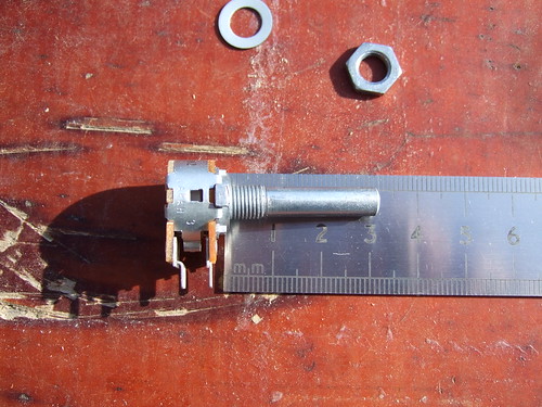
Volume pot with nut, washer and lug removed before cutting
I measured the spindle length with a metal rule, stuck the end I was removing in my workmate vice and then got busy with a hacksaw, remembering to catch the the pot once I'd cut though the spindle.
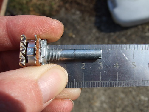
Measuring where to cut the spindle
Just make sure that you cut the right side of your pencil line or your spindle will be too short! Finish off the job with a file to take off any rough edges.
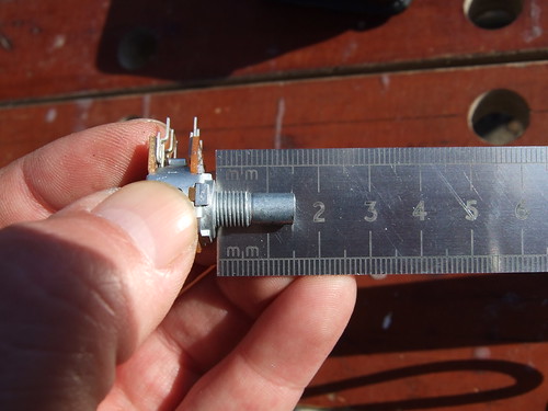
Spindle cut.
Graham recommends that you make a template by making a hole in a 15mm thick piece of MDF and using this to mark the spindle. For me at least, this wasn't necessary.
The final bit of preparation is to file a tag to remove the surface plating on the volume pot to allow the attachment of a ground wire.
Now that the volume pot is prepared, it's a matter of soldering it to the PCB. Once soldered in place, a ground wire (supplied) is soldered between the board and volume pot.
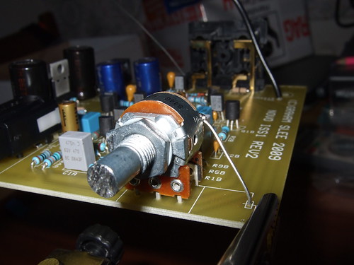
Volume pot attached. Note grounding wire.
I then soldered on an LED, a flying wire underneath the board and attached a couple of grounding wires in preparation for fitting the board into the case.
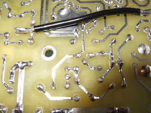
The flying wire underneath the PCB. Notice the wide spacing of the tracks and pads.
Completed board from the back. Note the grounding wires.
The board is complete! All components are now attached to the PCB.
This session lasted about an hour. The next session will cover constructing the case and installing the board.
I removed the nut and washer and used my side cutters to remove the anti-rotation lug. If you are using the Case Kit you need to cut the volume pot spindle to 15mm in length.
Volume pot with nut, washer and lug removed before cutting
I measured the spindle length with a metal rule, stuck the end I was removing in my workmate vice and then got busy with a hacksaw, remembering to catch the the pot once I'd cut though the spindle.
Measuring where to cut the spindle
Just make sure that you cut the right side of your pencil line or your spindle will be too short! Finish off the job with a file to take off any rough edges.
Spindle cut.
Graham recommends that you make a template by making a hole in a 15mm thick piece of MDF and using this to mark the spindle. For me at least, this wasn't necessary.
The final bit of preparation is to file a tag to remove the surface plating on the volume pot to allow the attachment of a ground wire.
Now that the volume pot is prepared, it's a matter of soldering it to the PCB. Once soldered in place, a ground wire (supplied) is soldered between the board and volume pot.
Volume pot attached. Note grounding wire.
I then soldered on an LED, a flying wire underneath the board and attached a couple of grounding wires in preparation for fitting the board into the case.
The flying wire underneath the PCB. Notice the wide spacing of the tracks and pads.
Completed board from the back. Note the grounding wires.
The board is complete! All components are now attached to the PCB.
This session lasted about an hour. The next session will cover constructing the case and installing the board.
A
Anonymous
Guest
Nice. 🙂
PJPro:used my side clippers to remove the anti-rotation lug.
Huh? The what?
PJPro:I then soldered on... a flying wire underneath the board"
Huh? A what? What's that doing?
PJPro:used my side clippers to remove the anti-rotation lug.
Huh? The what?
PJPro:I then soldered on... a flying wire underneath the board"
Huh? A what? What's that doing?
tractorboy:Nice. 🙂
PJPro:used my side clippers to remove the anti-rotation lug.
Huh? The what?
There's a lug on the volume pot which can be used to fit into a socket on a case front panel. It stops the pot from rotating when you turn the knob. This isn't necessary when you fix the pot to a PCB.
The side clippers = side cutters. Sorry, my mistake. I've corrected the post.
tractorboy:PJPro:I then soldered on... a flying wire underneath the board"
Huh? A what? What's that doing?
It connects two tracks on the PCB. I don't know if it was deliberate or a workaround. But there are two short solder spills on the board to accomodate the flying wire, suggesting the former.
A
Anonymous
Guest
Got it. Ta for the explanations. I was surprised that you had to cut down the volume pot. I guess I'd just assumed that it would be the correct length already. Still, I suppose they get fitted in various size cases.
A
Anonymous
Guest
This looks like a very interesting project indeed. I just finished my CMOY and already want to build something bigger, better...
I wonder, will this stop at the next one if I do it ? (tell me when you are finished 🙂
Now I know you probably did a very meticulous research before choosing the Novo kit, and do know that you started with tangent's cmoy. It would be very interesting indeed to know why did you not continue with tangent's PIMETA or PPA but chose this one?
Also did you see the DYNALO by Kevin Gilmore?
cheers,
m-leon
tractorboy:Got it. Ta for the explanations. I was surprised that you had to cut down the volume pot. I guess I'd just assumed that it would be the correct length already. Still, I suppose they get fitted in various size cases.
Yeah, I was surprised too. The instructions weren't absolutely crystal clear. I had to email Graham to confirm my understanding before I made the cut.
However, I hadn't needed to email him before this point...suggesting the instructions in the manual are pretty good.
Yeah, I was surprised too. The instructions weren't absolutely crystal clear. I had to email Graham to confirm my understanding before I made the cut.
However, I hadn't needed to email him before this point...suggesting the instructions in the manual are pretty good.
Norayr Matevosyan:
I wonder, will this stop at the next one if I do it ? (tell me when you are finished 🙂
Already looking for my next project. As a filler, I thought I'd do the Beresford mods. See here.
I am investigating the possibility of building a couple of linear power supplies for the Novo and the Beresford as my next project. I'm interested the Young-Jung Power Supply by Tangent. I'm in contact with the designer regarding suitability for the Novo and Beresford. The initial view is that the Beresford has too high a current requirement for the YJPS.
The other possibility is the SOHA II. This is a hybrid amp which uses both integrated circuits and valves. It has the advantage (from a DIYer perspective) that it utilises a low voltage circuit rather than the high voltages normally found in valve amps. The designer's website for this amp is here. Kits are available from Glass Jar Audio. Glass Jar Audio also have a number of other kits available, including the ultimate DIY heaphone amp...the B22.
Norayr Matevosyan:
Now I know you probably did a very meticulous research before choosing the Novo kit, and do know that you started with tangent's cmoy. It would be very interesting indeed to know why did you not continue with tangent's PIMETA or PPA but chose this one?
I did consider the PIMETA and PPA. The PIMETA didn't seem like enough of a jump in complexity for me...although I understand it can give very good results. For me, it was a toss up between the PPA and the M3. The advice I received from DIYers far more experienced than I was that M3 was a lot easier to troubleshoot if something went wrong....so I was going to go for that.
In the meantime, I stumbled across an annoucement that the Novo was going to be available as a kit. A few months went by and the 5 star review in WHFSV on the Novo reminded me of the kit. It's a complete kit so there's none of the hassle of finding the parts. I also thought it would make a good thread for the forum, so I went for it.
Interestingly, the thread for my Tangent CMoy variant has had a lot more views and responses than the Novo, so maybe I misjudged the level of interest in the Novo.
Norayr Matevosyan:
Also did you see the DYNALO by Kevin Gilmore?
No, not seen that one. I'll take a look.
A
Anonymous
Guest
PJPro:
Already looking for my next project.
Now you've got a nice steady hand you could try a gamma1 http://www.amb.org/audio/gamma1/
Someone else's photo diary of making one is here http://fault151.blogspot.com/2009/03/building-my-y1-mini-dac.html
looks like a nice project
Already looking for my next project.
Now you've got a nice steady hand you could try a gamma1 http://www.amb.org/audio/gamma1/
Someone else's photo diary of making one is here http://fault151.blogspot.com/2009/03/building-my-y1-mini-dac.html
looks like a nice project
Similar threads
- Replies
- 8
- Views
- 1K
- Replies
- 3
- Views
- 1K
- Replies
- 5
- Views
- 2K
TRENDING THREADS
-

-

-
Question What to do first? Stylus of preamp upgrade?
- Started by Feelio
- Replies: 5
-

-

-
-
Space.com is part of Future plc, an international media group and leading digital publisher. Visit our corporate site.
© Future Publishing Limited Quay House, The Ambury, Bath BA1 1UA. All rights reserved. England and Wales company registration number 2008885.
 Twitter