DIY Headphone Amp #2 - Graham Slee Novo

Page 3 - Seeking answers? Join the What HiFi community: the world's leading independent guide to buying and owning hi-fi and home entertainment products.

PJPro

New member
Jan 21, 2008
274
0
0
Visit site
zzgavin:
PJPro:
Already looking for my next project.

Now you've got a nice steady hand you could try a gamma1 http://www.amb.org/audio/gamma1/

Someone else's photo diary of making one is here http://fault151.blogspot.com/2009/03/building-my-y1-mini-dac.html

looks like a nice project

Yeah, methinks that surface soldered stuff looks way too difficult just yet.
 

PJPro

New member
Jan 21, 2008
274
0
0
Visit site
On with the build....

This session involved assembly of the case. The case is in four parts, comprising of the back and front panels and the top and bottom panels. The top and bottom panels also form the sides. Also included in the case kit is the volume knob, an earth attachment and self adhesive rubber feet.

Everything is grounded to the case. So, to insure a good contact between the front and back panels and the sides and top, you have to penetrate the case coating so that when the screws are tightened a continuous circuit is formed.

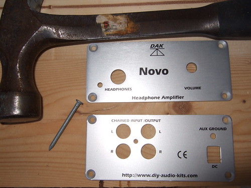
To do this, you "disturb" the countersinks which accept the screws. Graham recommends a small punch to do this. I used a suitably small nail and a hammer.

3453682622_d9db3dcc47.jpg

Front and back panels, galvanised nail and estwing hammer.

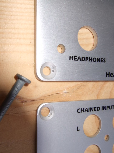
Using gentle taps with the hammer, I formed small indentations/ridges in the screw countersinks. I placed two of these in each countersink, ensuring they were positioned so that they would be covered up by the screw head.

3452872133_7904279c7f.jpg


The next step was to assemble the case grounding connection. This comprises of a bolt, some serrated washers, ordinary washers, a solder tag and a hex spacer. The instructions make the order of assembly clear. You just need to make sure the serrated washers are against the case, so that they bite into the surface when you tighten it up, ensuring a good connection to the case.

Once the case grounding connection is in place, you attach the back panel to the PCB. This attached to the phono block using a single screw.

3452876447_044229e17b.jpg

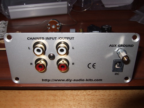
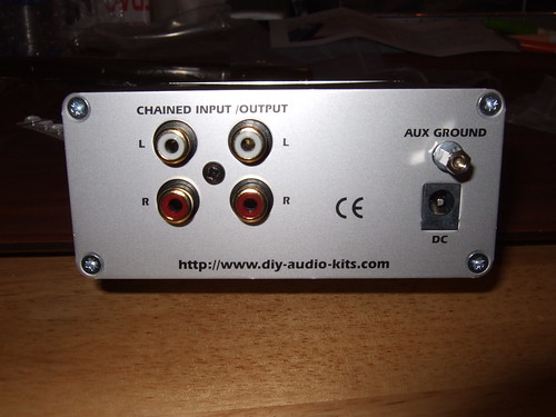
The back panel fitted to the PCB.

Note: the auxillary ground on the back panel is one end of the case grounding connection. The idea is that the auxillary ground allows the attachment of a earth wire if the user encounters any problems with mains hum.

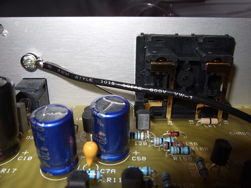
The grounding wires added in the previous session are soldered to the case grounding connection using the solder tag.

3452874209_7d14b46230.jpg

Grounding wires attached to back panel.

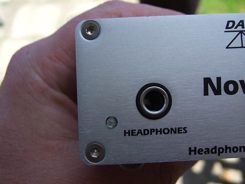
The bottom panel is slid onto the PCB, followed by the front panel. Ease the front panel on to ensure that you don't damage the LED. If you've made a bad job of fitting the LED, now is the time you'll find out. I followed the instructions and didn't encounter any problems. Use the supplied screws to secure the front and back panels to the bottom panel. Put the washer and nut on the volume pot spindle.

3453693410_13239a6297.jpg

Back, front and bottom panel enclosing the PCB.

I kept the screws and nut on the spindle fairly loose at this stage, to allow me to wiggle things around and get the top to fit. So, placing the top on, fit the screws and tighten everything up. Fit the volume knob. Stick on the rubber feet.

3453702054_3ce480f609.jpg

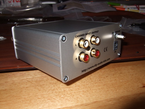
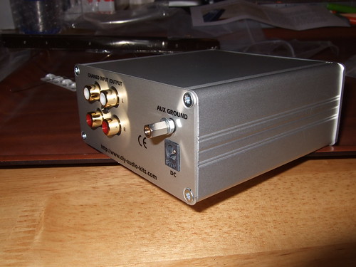
Completed Novo from the back, right.

3452889687_f7b8e3585e.jpg

Completed Novo from the back.

3452891869_9654b0c6d0.jpg

Completed Novo from the back, left.

3453695382_99420abff7.jpg

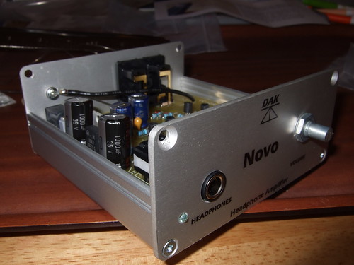
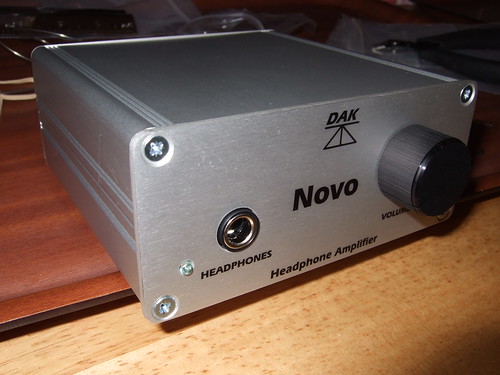
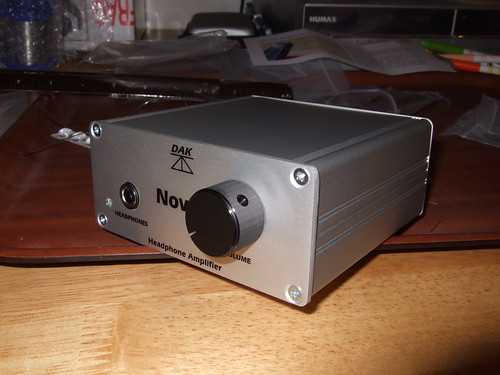
Completed Novo from the front, left.

3452882927_225b405a71.jpg

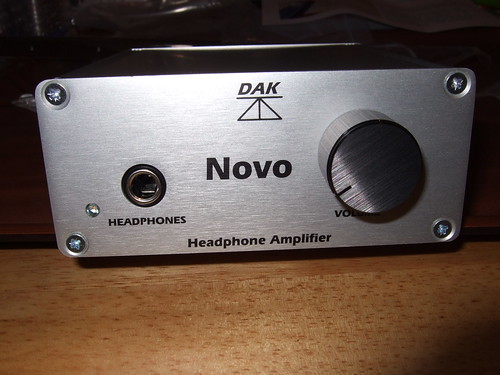
Completed Novo from the front.

3452885167_71ffc8b3c1.jpg

Completed Novo from the front, right.

3453708494_f8a63ab443.jpg

Waaaaahhhhaayyyy! AJPro celebrates completion of the build!

All that remained was to construct the power supply (very very simple, clip together design) and everything was done and ready for a listen....or was it? Not quite.....

This session took around 30 minutes.

In the next session I cover testing the build. Oho.
 

idc

Well-known member
PJPro:.... Interestingly, the thread for my Tangent CMoy variant has had a lot more views and responses than the Novo, so maybe I misjudged the level of interest in the Novo.....

PJ, I don't think so. The CMoy build was so detailed and answered so many questions that this thread has maybe suffered. But it has been an excellent read so far, with really good pictures.
 
A

Anonymous

Guest
Congratualtions on the build! Now how does it sound !?

P.S. Cute Glasses :)
 

PJPro

New member
Jan 21, 2008
274
0
0
Visit site
Sorry. I haven't forgotten this thread and will complete it. I've been busy doing stuff around the house and researching my next project.

In fact the testing stuff is the most important bit of the whole build, where I did encounter a significant issue and spend untold hours trying to sort it. A simple solution has been identified......so don't let this put you off. There is not an issue with the kit, so as long as you follow the instructions you'll be OK.

I'll update some time during the week.
 
A

Anonymous

Guest
Calling PJPro... I hope you haven't electrocuted yourself with a dodgy soldering iron...
 

PJPro

New member
Jan 21, 2008
274
0
0
Visit site
No. But thanks for your concern. I'm having trouble finishing this thread off but I will do it. I planned to do it tonight but I had the in-laws round today and was helping out someone with a foobar issue.

I haven't got round to modding my Beresford either.

I've selected the next project and the bits are on their way from the States. I'm going to build a linear power supply for the Beresford using Tangent's TREAD.
 

PJPro

New member
Jan 21, 2008
274
0
0
Visit site
To finally finsh off this thread, I'm going to make this short and sweet.

The kit requires that the voltage be measured in around 20 places to ensure the correct operation of the amp. There's a fairly narrow tolerance i.e. 0.1VDC.

I duly measured the voltages and found one value on both channels was way off. I should have been seeing a voltage of 5.7V but was actually reading 4.9V. There next ensued many, many hours checking the board for problems.

This is where the photos came in really handy. I could zoom right in and compare before and after photos of the board to ensure that I hadn't created any bridges.

There was one point where it looked like I had damaged two transistors (one per channel) and was poised to remove them, with Graham sending me replacements in the post. It was all looking a little desparate.

Finally, the problem was tracked down to my multimeter! Multimeters have their own internal resistance and when taking measurements in an areas of the circuit with high resistance, the resistance of my multimeter was acting to reduce the voltage....giving me the wrong reading.

I confirmed this by taking the amp into work and using a Fluke (top quality) multimeter to take the reading. Graham confirmed at his end by using a cheap meter and got similar incorrect result as I had with my cheap meter.

For those that follow, the test point of 5.7V between R4, R2 and R3 is the area of difficulty. Cheap meters may give a lower reading than 5.7V. My cheap meter indicated 4.88V.

The double check is to measure the voltage across the emitter and base of the Q1 transistor. You should see a drop of 0.6V. Actually place your red probe on the emitter and black probe on the base (at the same time) to take the reading.

That's it. Job done.

I'd like to thank Graham at this point for the advice he provided during the difficulties encountered during testing.
 

PJPro

New member
Jan 21, 2008
274
0
0
Visit site
I have noticed very minor issue with the build. The blurb says the case is exactly the same as the manufactured version except for the graphics.

However, I've noticed that the manufactured version uses torx screws rather than the posidrive screws supplied with the kit.

I'll write an email to Graham to see if he can send me some out (for a small fee).
 

PJPro

New member
Jan 21, 2008
274
0
0
Visit site
PJPro:I have noticed very minor issue with the build. The blurb says the case is exactly the same as the manufactured version except for the graphics.

However, I've noticed that the manufactured version uses torx screws rather than the posidrive screws supplied with the kit.

I'll write an email to Graham to see if he can send me some out (for a small fee).
Seems they are actually allen key screws. See Graham's reply below.

Graham Slee

The screws on the production unit are stainless socket head screws for use with a 2mm AF allen key and most local nuts and bolt suppliers have them for pence. Universal description M3 x 10 stainless csk (countersunk) skt (socket) hd (head) set (setscrew).

So there you go.
 
A

Anonymous

Guest
PJPro, Great thread, which just confirms that if I want a Novo I'll need to save a bit longer and buy a factory built unit.
 

PJPro

New member
Jan 21, 2008
274
0
0
Visit site
qwerty69:PJPro, Great thread, which just confirms that if I want a Novo I'll need to save a bit longer and buy a factory built unit.
Which bit gives you cause for concern?
 

PJPro

New member
Jan 21, 2008
274
0
0
Visit site
On re-reading this thread I realise that I haven't provided a verdict on the kit. So......

The kit basically provides everything you need (solder excluded) to build the amp. Only basic tools are required. The instructions are easy to follow with the only real stumbling block being the identification of the resistors from the colour bands. My guide, however, plugs this oversight.

Does the amp sound any good? Well, I certainly feel that it is an improvement on my Beresford. However, I suspect that it is being restrained to a certain extent by my headphones (Grado SR80) and feel there is more to give. The mag recommends Grado SR325i for this amp, if memory serves.

Would I recommend this kit to someone who has never done this sort of thing before? Well, that depends. If you are the sort of person who can follow a recipe with precision, is patient and has a modicum of practical ability, then yes....go for it. If not, then it's a fair bit of cash to splash with the risk of nothing to show for it (although Graham will, apparently, take your kit and build it for you at a cost).

Bottom line - a well crafted kit, easy to build, good instructions (excepting identification of resistors) and satisfying end product. A better power supply (kit or wallwart) would be gratefully recieved.
 

PJPro

New member
Jan 21, 2008
274
0
0
Visit site
PJPro:PJPro:I have noticed very minor issue with the build. The blurb says the case is exactly the same as the manufactured version except for the graphics.

However, I've noticed that the manufactured version uses torx screws rather than the posidrive screws supplied with the kit.

I'll write an email to Graham to see if he can send me some out (for a small fee).
Seems they are actually allen key screws. See Graham's reply below.

Graham Slee

The screws on the production unit are stainless socket head screws for use with a 2mm AF allen key and most local nuts and bolt suppliers have them for pence. Universal description M3 x 10 stainless csk (countersunk) skt (socket) hd (head) set (setscrew).

So there you go.
I was in a nut and bolt warehouse the other day, getting some bits for the power amps, so I took the opportunity to get some stainless steel allen bolts for the Novo.

3792786377_9606e50eb3.jpg

Novo with stainless steel allen bolts

Have to say I'm a little bit disappointed. As far as I can tell, there is no detectable improvement in the quality of the sound produced, although I accept an improvement may be experienced by others. They look nice though.
 
A

Anonymous

Guest
Tempted to write a reply on burn-in characteristics of allen bolts - but no I won't
emotion-16.gif
 

TRENDING THREADS

Latest posts