need switch to alternate L & R channel in different rooms

onthewater1

Active member
Oct 29, 2024
14
4
25
Visit site
I’m going to try this one more time…but this time I’ll try to include all the necessary information...i hope.

I have a Rotel RKB-D8100 amp with 8 channels pushing four sets of speakers.
I have two speakers in room 1 and two speakers in room 2, the other two sets are not important for this discussion.
When I’m in room 1 I have stereo sound, when I’m in room 2 I have stereo sound. In my open concept house between rooms 1 & 2 is my kitchen. When I’m in the kitchen I’d like to have the left channel coming from room 1 and the right channel coming from room 2.
I can accomplish this by manually switching the left wires for room 1 with the right wires from room 2 in the back of the amp but it’s inconvenient.
I’m wondering if anybody is aware of a switch that would accomplish this?
The Russound AB-2.2 doesn’t do this.
Not sure if this is pertinent but just in case...I have four sonos connects connected to the four sets of speakers all controlled by the sonos app in conjunction with spotify on my phone.
Thanks!
 

Gray

Well-known member
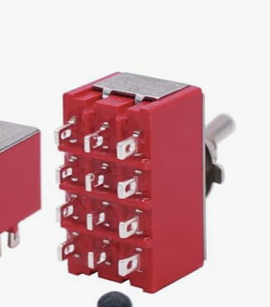
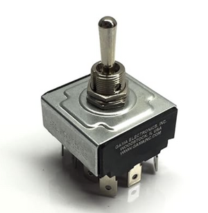
The switch that Vincent has linked to will do what you want.
It is wrongly described in the description as a 12 pole switch.
It is a switch with 12 contacts.
But, importantly for your purpose, it is actually a 4PDT (4 pole, double throw) switch.

You'd need to be handy with a soldering iron - if you're up for that I'll draw you a wiring diagram.....but it won't be pretty.
 

onthewater1

Active member
Oct 29, 2024
14
4
25
Visit site
The switch that Vincent has linked to will do what you want.
It is wrongly described in the description as a 12 pole switch.
It is a switch with 12 contacts.
But, importantly for your purpose, it is actually a 4PDT (4 pole, double throw) switch.

You'd need to be handy with a soldering iron - if you're up for that I'll draw you a wiring diagram.....but it won't be pretty.
that would be great, thank you!!
 
  • Like
Reactions: Gray

Gray

Well-known member
It's past midnight now, so later today for the wiring to the switch (y)

If you go for the switch, the use of the usual 2.5mm minimum stranded cable won't be practical for your soldering.
Ideally you want thinner, solid core, through the holes in the solder tags , maybe run to 8 chassis sockets (on the same box) for plugs from your amp and speakers.

The switch depends on two stereo outputs from your amp (we'll call them outputs A & B) being on simultaneously.
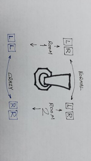
Then you can have stereo to both rooms OR Left in one room, Right in the other, depending on the 2-position switch.
 

Gray

Well-known member
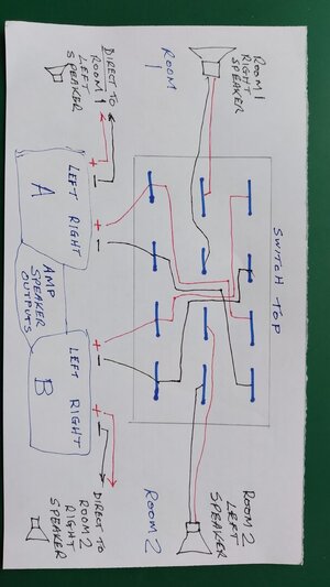
...If you wire that switch like this:
IMG_20241110_141000_MP.jpg
You will end up with this:
IMG_20241110_141843_MP.jpg

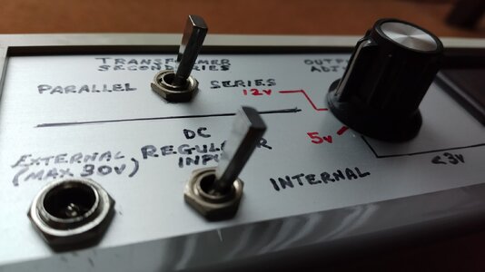
I went with the flat toggle:IMG_20241110_111243_MP.jpg
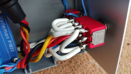
But the switch body is the same as yours would be:IMG_20241110_111953_MP.jpg
Whites are the link wires.
(You can see why thin wire is a good idea)

That does your 2 speakers left in one room, 2 speakers right in the other.
But if you could settle for just one speaker playing each channel in each room - you could do it with a ready-made, source to A or B switch box.
 

onthewater1

Active member
Oct 29, 2024
14
4
25
Visit site
...If you wire that switch like this:
View attachment 7783
You will end up with this:
View attachment 7784

I went with the flat toggle:View attachment 7785
But the switch body is the same as yours would be:View attachment 7786
Whites are the link wires.
(You can see why thin wire is a good idea)

That does your 2 speakers left in one room, 2 speakers right in the other.
But if you could settle for just one speaker playing each channel in each room - you could do it with a ready-made, source to A or B switch box.
Thank you Gray. Greatly appreciate your time, diagram etc!!! If your ever in Naples FL, US, beers on me.
Thanks again.
 
  • Like
Reactions: Gray

onthewater1

Active member
Oct 29, 2024
14
4
25
Visit site
Thank you Gray. Greatly appreciate your time, diagram etc!!! If your ever in Naples FL, US, beers on me.
Thanks again.

hello, I guess I'm not done with you.

another question, not sure what this means " maybe run to 8 chassis sockets (on the same box) for plugs from your amp and speakers."?

Will your answer, answer my question about how to transition from multi strand to solid wire?

I found two options for 4PDT switches, one will need to solder the other has quick connects, your thoughts?

Thanks!
 

Attachments

  • Screenshot 2024-11-14 at 1.43.18 PM.png
    Screenshot 2024-11-14 at 1.43.18 PM.png
    105.6 KB · Views: 2
  • Screenshot 2024-11-14 at 1.42.28 PM.png
    Screenshot 2024-11-14 at 1.42.28 PM.png
    263.5 KB · Views: 2

Gray

Well-known member
another question, not sure what this means " maybe run to 8 chassis sockets (on the same box) for plugs from your amp and speakers."?

Will your answer, answer my question about how to transition from multi strand to solid wire?
Yes.
4mm chassis sockets such as these:
4 reds and 4 blacks mounted somewhere on the same box as your switch - would allow the connection of 4mm banana plugs (commonly used on stranded speaker wire)

Then from the back you would run wire to your switch.

Though the black switch in your photo would not limit you to thin wire, as the push-on crimp tags would accept thicker stuff - meaning you could do without sockets and run wire direct to the switch

It looks as if it could be a centre off type - as long as it switches a common 4 poles between 2 other, separate sets of 4 contacts, either side of its off position.

Make sure that you can identify the poles / appropriate contacts and wire it correctly, as you really don't want short circuits or incorrect phasing (reversing red / black wires).
 

onthewater1

Active member
Oct 29, 2024
14
4
25
Visit site
not sure what this means "It looks as if it could be a centre off type - as long as it switches a common 4 poles between 2 other, separate sets of 4 contacts, either side of its off position" you mention in your diagram "switch top", is the "switch top" identifiable in the switches? sorry for my ignorance...
 

Gray

Well-known member
If you look at my diagram, you will see 3 horizontal rows of 4 contacts.
Each vertical column of 3 contacts is a separate pole - the poles never connect to each other.

The central 4 horizontal contacts are known as the common ones.

When the toggle is DOWN* the 4 common contacts are connected to the upper row of contacts.
When the toggle is UP* the 4 common contacts are connected to the lower row of 4 contacts.

*With reference to my 'switch top'.

They don't mark 'top' on the switch - because they don't know whether you want up or down toggle to be LL/RR - we've got downward toggle selecting LL/RR - so what I've marked as 'top' is the top for your purpose.


When a switch has a centre off position, the common row connects to nowhere.
Such a switch might be marked / described as
ON-OFF-ON
It's a 3 position switch, whereas the red switch has only 2 positions, ON-ON.
You just need to understand that it's those common 4 contacts that are effectively ON or OFF in those descriptions.

If you follow the diagram you will see why your speakers connect to the common row.
(Because they're the things that need different outputs connected to them - the switch will be doing what you're currently doing with your multiple plug swapping 👍).
 
Last edited:

onthewater1

Active member
Oct 29, 2024
14
4
25
Visit site
If you look at my diagram, you will see 3 horizontal rows of 4 contacts.
Each vertical column of 3 contacts is a separate pole - the poles never connect to each other.

The central 4 horizontal contacts are known as the common ones.

When the toggle is DOWN* the 4 common contacts are connected to the upper row of contacts.
When the toggle is UP* the 4 common contacts are connected to the lower row of 4 contacts.

*With reference to my 'switch top'.

They don't mark 'top' on the switch - because they don't know whether you want up or down toggle to be LL/RR - we've got downward toggle selecting LL/RR - so what I've marked as 'top' is the top for your purpose.


When a switch has a centre off position, the common row connects to nowhere.
Such a switch might be marked / described as
ON-OFF-ON
It's a 3 position switch, whereas the red switch has only 2 positions, ON-ON.
You just need to understand that it's those common 4 contacts that are ON or OFF in those mins descriptions.

If you follow the diagram you will see why your speakers connect to the common row.
(Because they're the things that need different outputs connected to them - the switch will be doing what you're currently doing with your multiple plug swapping 👍).
I understand, thanks for the detailed explanation. I really can't thank you enough for your time, diagrams and explanations.!!
My girlfriend and I were sitting on the couch last nite listening to music between the two rooms and we both agreed it would be nice to have L in one room and R in the other.
What kind of sound system do you have? Are you in the UK?
 

Gray

Well-known member
My girlfriend and I were sitting on the couch last nite listening to music between the two rooms and we both agreed it would be nice to have L in one room and R in the other.
Well good luck with making a convenient switcher.
Unless somebody copies your idea, you can be fairly sure your specific switchbox will be unique in the world 😉

Yes, I'm in south-east England with English- made amp (Cyrus) and speakers (PMC).
The plan is to buy a product from your land soon (even if it is, probably, made in China) - a Wiim Ultra.

Whichever way you listen, enjoy your music 👍
 

TRENDING THREADS

Latest posts