- Apr 19, 2008
- 56
- 0
- 0
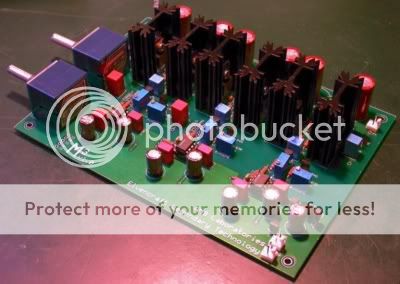
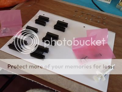
Thought this maybe of interest to some of you - I recently built an M3 headphone amplifier over the month of October last year - this is a log in a series of posts documenting the process. These posts will be quite long but I'll try and keep them as concise as possible. ~ Introduction ~ I'm relatively new to DIY electronics, my first attempt was around Christmas of 2009 when I built a Starving Student valve hybrid amp, until then I had no experience and very little knowledge about electronics in general. I have since built another Starving Student (a 12AU7 design) and a few CMoys. The M3, or M cubed as its pronounced, is a high-end three channel amplifier featuring a MOSFET output stage on each channel, hence its name. As this is a non-commercial design, you either have to build it yourself or commission someone to build it for you. The schematic is open source but the printed circuit board needed to build the amp is available from AMB, an organization that specialize in DIY audio and are also responsible together with members of the DIY community for the design.
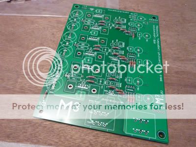
 Here's a link with more information - http://www.amb.org/audio/mmm/ ~ Design & Casework ~ The desire to build this amp was quite impulsive, the idea having been really at the back of my mind, I wanted to do something a bit further up the chain and had been considering a PIMETA as the next project. The idea for the case was something that I wanted to try for a while, so around the end of september while at work I spotted some 5mm thick aluminum lying around the guillotine, these were once used for temporary bus stop signs, they each measure around a foot square, not even knowing what the sizes should be I roughly estimated and cut 2 at 8" by 10" and 2 at 8" by 4", this is where it all came together and I decided to commit to this project! On returning home I checked the size of the PCB - 5" by 7" - so plenty of room, also I quickly made a 3D mock-up to give me an idea how it would look.
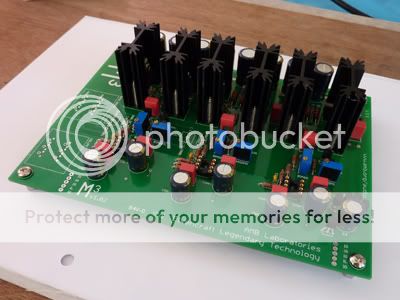
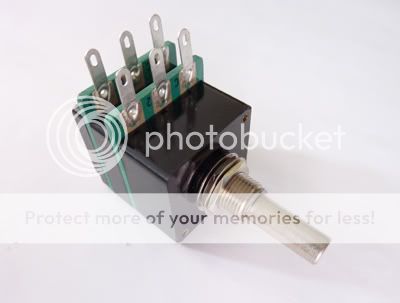
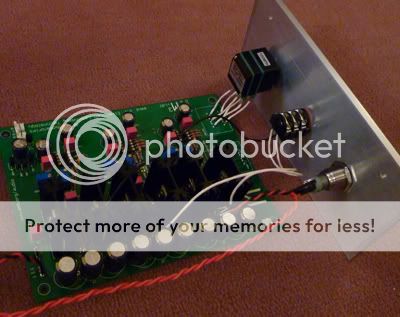
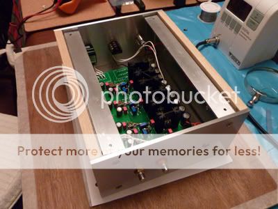
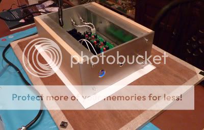
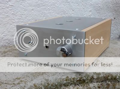
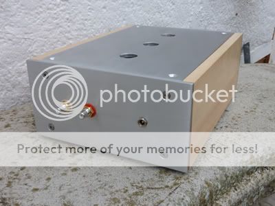
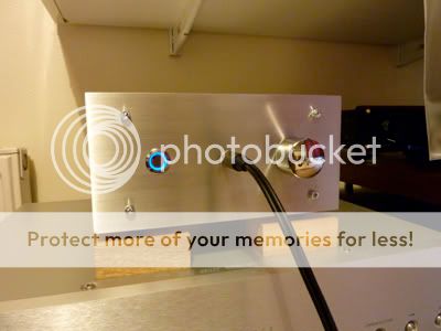
 I wasn't originally going to put holes in the top and the volume was going to be centered with the headphone jack to the right, but form must follow function - from researching the amp six MOSFETs put out a bit of heat so I had to have a way for air to flow though the case, I also drilled half a dozen 1/2" holes in the base. The volume pot benefits from being mounted as close, if not, on the board itself otherwise there is the prospect of the wires picking up interference. As you can see there is space for two pots on the pcb, one volume and the other a variable bass boost, I decided not to go with this feature. After a lot of sanding - firstly the thick coating had to be removed, I could see what kind of dents and scratches were on the plates, then after filing the edges, carefully started smoothing them out with higher grade paper and always trying to rub along the "grain". I used a small metal block wrapped with production paper for the edges after filing to get the dimensions as close as possible. To hold the whole thing together I used galvanized steel brackets folded at each end as well as the bottom - this would allow the front, bottom and rear panels to be bolted (countersunk for the later two) and Instead of folding the top I decided on using two pieces of 1/8" thick 1" aluminium angle, that were tapped into so that they could be attached with machine screws, the wood sides also are mounted with screws from inside onto the brackets.
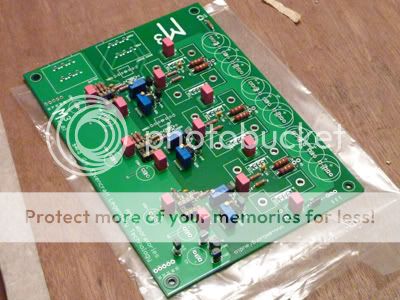
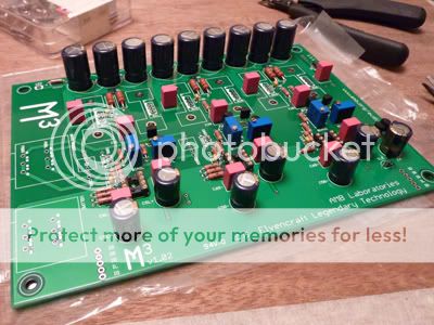
 For the finish I decided on a brushed look and light coloured wood side panels to give the amp a fresh clean look. After the box was test assembled to make sure all was well, the aluminium panels were then prepared for brushing, this is something I'd never done before. A side note - I did the brushing/finishing and started assembling the pcb on the 29th October, so the case took around a month, on and off to make. After polishing the panels with 600 grade wet & dry, I then set up a work-mate type bench by wrapping masking tape backwards around one top so that the sticky side is facing outwards, this would hold the panels in place. I then wrapped some 80 grit production paper around a piece of wood wide enough so that I could hold it both sides, this then would allow me to roll my fingers round so that the top of my nails could press against the edge of the plates and keep the block straight as I pull it towards me. It took a bit of practice, but I gradually got the hang of it and the process didn't take as long as I thought it would. To finish I used some fine grade Scotch-brite to smooth out the surface a little, except for a couple of "witness marks" cause by slight sideways movements of my hands, they turned out pretty decent.
 All that was left to do was to seal them with a coat of lacquer, the plates were thoroughly washed in washing-up liquid to remove dust, dried and then very carefully cleaned with Isopropyl alcohol to remove finger marks, etc. Then a couple of coats of Plasti-Kote Metal Sealer were applied to protect the surfaces from scratches and oxidization. That's it for now - next we'll start on the electronics!


 Twitter