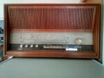
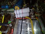
I have a FRANK pram 30 watts Ultra-linear Stereo tube amplifier, in which I am replacing the selenium full wave rectifier with a diode full wave rectifier, I am also replacing the selenium bias rectifier with a diode, as well as replacing the electrolytics.
The details of the amp are below.
I have a schematic, but it is missing some vital info. The selenium rectifier had a forward DC resistance of 295K and was pushing out 345V. As selenium rectifiers don't age well, I don't know if the 345V being output is too high or too low. As the forward resistance of the diode rectifier is much lower, the output is going to be much higher. What I am trying to find out is what the original design voltage should be. I'm not worried about the bias voltage as it's for the 4 x EL84 so should be about 11.5V I'm guessing.
Does anyone have any info on this amp?
Made in Belgium by the FRANK factory at the end of the 1950-early'60.
It uses an ULTRA LINEAR circuit, and the famous beige Philips-Mullard mustard capasitors.
Still complete factory original, all cap's and resistors are still original.
These FRANK amplifiers were all handmade.
This one was made March 1961.
2 x 15 Watt.
The tubes are : 4 x ECC 83 / 2 x ECC 82 / 4 x EL 84.
Works on 110 & 240 volts , speakers 8 - 16 Ohms


New diode rectifier.

The details of the amp are below.
I have a schematic, but it is missing some vital info. The selenium rectifier had a forward DC resistance of 295K and was pushing out 345V. As selenium rectifiers don't age well, I don't know if the 345V being output is too high or too low. As the forward resistance of the diode rectifier is much lower, the output is going to be much higher. What I am trying to find out is what the original design voltage should be. I'm not worried about the bias voltage as it's for the 4 x EL84 so should be about 11.5V I'm guessing.
Does anyone have any info on this amp?
Made in Belgium by the FRANK factory at the end of the 1950-early'60.
It uses an ULTRA LINEAR circuit, and the famous beige Philips-Mullard mustard capasitors.
Still complete factory original, all cap's and resistors are still original.
These FRANK amplifiers were all handmade.
This one was made March 1961.
2 x 15 Watt.
The tubes are : 4 x ECC 83 / 2 x ECC 82 / 4 x EL 84.
Works on 110 & 240 volts , speakers 8 - 16 Ohms


New diode rectifier.


