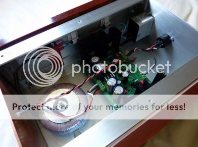
β22 Headphone Amplifier ~ Build Log ~

lonely boy

New member
Apr 19, 2008
56
0
0
Visit site
For the last couple of months I have been focusing my attention on my current project, a β22 (beta22) headphone amplifier and σ22 (sigma22), its accompanying linear regulated power supply.

You join me still in the process of building the casework and ferreting away the multitude of parts needed.

For those unaware, this is a highly regarded high-end DIY only design much liked for its transparency and power. Like my previous M³, this is not commercially available so it's pretty much up to you to put one together yourself. I'm really curious to see if this will be an improvement over the aforementioned amp, the promise of more power to allow for a better sound stage and imaging as well as smoother sound has me interested enough to invest my time and money in this project. Hope it will be worth it!

For now I'm going to concentrate on layout and case design of the amplifier - a bit backwards I know, but a significant amount, if not the most work in a DIY build goes on the casework. I'll talk about the electronic side of things and technicalities as best as I can later on when I start populating the boards, hopefully around Easter time.

~Design~

Firstly the modular design of the β22 is quite flexible, each board contains one channel only allowing for different configurations -

- as a standard two channel amp with a passive ground (two boards)
- two channel with an "active ground" (three boards)
- four boards for balanced, one for each phase of both channels (L+,L-,R+,R-)
- balanced and single-ended operation in the same unit (four or six boards)

Some people have also used dual σ22 power supplies for separate channels, of course all of this adds to the complexity and cost of the build.
Also worth noting is that the β22 can be used as a pre-amp and speaker power amp too, so you really need to consider your options carefully before attempting to build one.

As in this case I'm not interested in a balanced design and I'd like to keep things as compact and simple as possible I decided on a 3-channel single PSU configuration.

Originally I was not going to build any casework, instead the σ22 was going to be housed in a smallish Hammond enclosure and the amp would go in a medium sized HiFi 2000 Galaxy Maggiorato case from Modushop, all I would need to do was simply drill a few holes...

But as I'm mad and like to make things, I eventually decided on a design for the cases.

early-case-b22.jpg


I began getting some ideas together around mid January. Originally I was going to use 5mm aluminium plate for the top and base of each case as well as 10mm thick copper for the face plates and 5mm for the back, but working with thick metal can be a pain, especially drilling and mounting panel components, so sensibly I ordered 3mm sheet instead. The sides are made from any wood I can get my hands on, in this case a couple of chopping boards that I've stained and varnished, I may see if I can find something a little nicer in the future as I'm not totally happy with the way they look at the moment.

b22-01.jpg


This is the design that I eventually decided on, it is slightly reminiscent of the older gold Sony ES components. I like the look of copper so I kept that just for the front panels. As aluminium is easy to work with, the panels that need the most drilling will be made from it, this should contrast nicely with the dark wood and copper to give the amp a minimalist but interesting look.

The internal components will be laid out like this .

b22-02.jpg


Firstly the PSU - This enclosure will contain the σ22 printed circuit board and transformer. I'm using a filtered IEC module from Schurter for the power inlet. As I still consider myself a novice and have never before now dealt with live voltages this seems to be the tidiest and safest way to work. This unit contains the power switch, fuse holder and IEC power socket in one device, the transformer primaries simply attach to the live and neutral connectors and the earth is bolted to the case.
The outgoing DC power leaves the PSU via a Neutrik PowerCon socket on the rear, this is a good quality locking connector designed especially for power applications.

The amp enclosure will house the three PCBs from the middle to the front of the unit. I've decided to mount the selector switch and volume pot on a bracket at the rear, both will be connected to knobs mounted on the front panel by 6mm extension rods. The PSU and amp will be connected together by a 3-conductor umbilical, this contains the V+,V- and power ground wires.

That basically covers the design, next we'll concentrate on the construction of the cases.
 

lonely boy

New member
Apr 19, 2008
56
0
0
Visit site
idc said:
Work of art in the making.

Thanks for the kind words! And apologies folks for the delay posting.

Originally I planned around two months for the fabrication of both cases, including as much drilling as possible. My M³ took a month from conception to completion, it's surprising how much work there is!

The first thing I began work on was, of all things, the wood sides. I spotted some chopping boards while I was shopping, they were the right thickness so bought two. Cut them both length ways to give me four pieces, these were then cut to the length needed, the ends rounded off and then the width planed down. Each measured 12" x 4 1/2" - the maximum height and depth dimensions of the enclosures.

Similarly to the previous build everything is held together by the side brackets - I then cut 4 pieces of 1/8" (3mm) thick aluminium taking away just over 1/8" off each edge to allow for the panels to sit flush with the wood sides, 1" angle was then bolted to the top, bottom and ends of each plate by countersunk m4 bolts.

b22-03.jpg


After cutting the various outside panels at the same 8" width and their respective depth or height, taped the boxes together to test the fit.
b22-04.jpg


Now it's time start measuring and drilling the umpteen various holes for the panel mounted components and air vents, etc.

P1020853.jpg


- One of the top panels after drilling the 30mm air vents.

Most likely, when looking at the back of an audio component, the power inlet will be on the right and usually the audio inputs/outputs will be located on the left side of the unit. This is of course is simply to keep the AC wiring and the transformer away from the audio signal. I've stuck with this layout and placed the DC in the middle of the PSU and amp so even if both are laid down side by side (with PSU to the left) or on top of one another, non of the wiring should cross any other. That then means the input selector will have to be located on the side of incoming signal and the volume pot on the opposite side of the amp.

After all the holes have been drilled I can then remove the burr, clean up the panels and prepare for brushing and finishing them. I used the same basic method as before, of pulling 60 grit production paper wrapped round a block of wood repeatedly towards me, then finishing with a couple of coats of clear lacquer.

P1020988.jpg


P1020991.jpg


One thing I wanted to avoid was having visible bolt heads on the face plates, so these were bonded to the fixing brackets with Terostat 9220 automotive panel adhesive.
P1020985.jpg


I've chosen to mount both controls at the rear of the unit to keep the signal paths short, even so It's recommend that the length of the wire after the pot must be kept as short as possible, as the high impedance of the cable will pick up noise. I won't know for sure until I've actually build the amp and got it working if or how much interference it will pick up, as my case is quite small I'll have limited room for routing the wiring so there is a possibility I will have to use shielded wire.

b22-12.jpg


I ordered a couple of shaft extension kits that included the rod, mounting bracket, coupler and mounting bush, they were a little rough around the edges... but nothing that a file couldn't fix.

The input switch is made by Seiden, it's of very good quality. I've used a cheap ALPS pot just as a pattern, I haven't decided yet if i'll use another TKD pot or a stepped attenuator this time, I'm rather tempted to try one from Khozmo
P1020917.jpg


I like the look and feel of the knobs from Audio Note, these are 30mm diameter chrome plated solid brass.

That pretty much covers the case work for now.
 

lonely boy

New member
Apr 19, 2008
56
0
0
Visit site
Crossie said:
This is a great thread. I am looking forward to the next instalment. Thanks.

Cheers Crossie - glad you're enjoying it.

idc said:
My attempt to make a Cmoy was a complete failure, I am tempted to try again.

I had problems with my first Cmoy too, ended up having to sling it away. But I've made four of them now and they all work fine! So it's worth giving it another shot.
 

Olli1324

New member
May 28, 2008
48
0
0
Visit site
Fantastic! This is the amp I have built and use. I went for the 2 case, 1xo22 and 3 channels of B22 config, in Glaxay Mag. cases from modushop. It is great to see you doing the case work from scratch - I'm proficient in the workshop but never had the patience to design and build them myself.

If it helps, I used the following transformer from Conrad Electronics:

http://www.conrad.com/Toroidal-transformer-2X30V-80VA.htm?websale7=conrad-int&pi=518536&ci=SHOP_AREA_17430_2170280&Ctx={ver/7/ver}{st/3ec/st}{cmd/0/cmd}{m/websale/m}{s/conrad-int/s}{l/int/l}{sf/%3Cs1%3E518536%3C/s1%3E/sf}{p1/c35bce154ca6036449b8ced3737fd0fd/p1}{md5/5096f873325dd20e4bd9bc9087484d7d/md5}

Fits the bill just right and isn't too dear.

It was great fun building soldering the boards - the first one I built, though, I didn't fully appreciate the sheer number of components!
 

lonely boy

New member
Apr 19, 2008
56
0
0
Visit site
Just a quick update.

I've just put an order in for a Khozmo 50k stepped attenuator, this thing costs $179 - Can't wait to get my hands on it!

khoz_front.jpg


Also I'm just about to finalise my (hopefully) last order from Mouser for most of the remaining parts. The only thing I'm struggling to find is a suitable transformer. If everything goes to plan, I can start building it next weekend.
 

lonely boy

New member
Apr 19, 2008
56
0
0
Visit site
Brilliant - I've been looking everywhere but could only find 2x25v types, this is exactly what I've been after, thanks for the link.

Yep the casework is really time consuming - still haven't finished it even after nearly three months, also I realise now that they could be just a little bit bigger!
 

Olli1324

New member
May 28, 2008
48
0
0
Visit site
Pleasure
smiley-wink.gif


The sheer size of the B22 always amazes me - 2 cases of nearly the same size as my integrated speaker amplifier. Weighs more, too. Stark difference to the size of the headphone amplifier which fits in those tiny iPod Nanos!
 

lonely boy

New member
Apr 19, 2008
56
0
0
Visit site
Time to actually stuff the boards!

I began by checking the parts I had against the parts list and ordering them appropriately, ie R1, R2, etc. All four of the boards, including the sigma, were done at the same time, so all resistors fitted, than diodes, etc.

P1030014.jpg


P1030071.jpg


As usual, the lowest in height components go in first.

P1030135.jpg


The sigma PCB. The ground planes on all the boards are quite thick and require a little more heat and the use of flux for a proper joint.

P1030132.jpg


Things are shaping up nicely! Actually no they aren't, this is where I made another bodge. Didn't know it at the time.

P1030159.jpg


Almost complete, just the MOSFETs and heatsinks need to be fitted, and then the problems start!
 

lonely boy

New member
Apr 19, 2008
56
0
0
Visit site
Time for some pretty pictures and my first bodge.

P1030001.jpg


Test fitting of the three amp boards, it's a bit tight in there...

This is what happens when you don't think things through properly, the case is obviously too small, there isn't sufficent space for proper ventilation. This isn't a complete disaster as I drilled holes for mounting two boards in case I decided just to build a two channel version.

The problem stems from not having the PCBs at hand when designing and making the case, lesson learned, it seems that it's a good idea to have everything you will need beforehand so you know how exactly things will physically fit together.

The case needs to be much bigger than you think it needs to be for accessing the fiddly bits, even though I have small hands working in some parts of the case was a nightmare.

P1030005.jpg


This is the intended method for mounting, the bolts are countersunk into the angle.
 

lonely boy

New member
Apr 19, 2008
56
0
0
Visit site
I know this is an old thread but as this project is now officially completely finished (hurrah!) I thought that it was high time we had an update.

The amp has been functioning happily since July 2011, unfortunately a combination of problems with the build and life in general getting in the way contributed to me loosing interest in this project a number of times.

According to my notes, work started on the actual electronic bits around early May. This involved, firstly, filling the PCBs with a plethora of components. What should have been the easiest and therefore most boring part of the build turned out otherwise!

One factor contributing to the difficulty and time of a build is sourcing the parts and sufficent numbers thereof. As mentioned before, the b22 features a lot of components, most are easy to obtain and are reasonably priced, such as resistors and capacitors but we are dealing with a complex discrete design and that means finding an abundance of the various types of semiconductors.

Very basically three types of transistors are used over three stages.

Firstly we will find the J-FETs (Junction Field Effect Transistor) in the input stage, these have low operating noise but also are useful as they have a high input impedance and present a low output impedance to the next stage, so they can be used as a buffer as well as allowing direct coupling.

Secondly the voltage gain stage features BJTs (Bipolar Junction Transistor), these are the simplest (basically two diodes) and earliest type of transistor. This is where the incoming signal voltage is multiplied, therefore making it louder. In this build I've decided to set the gain at five times the input voltage.

The output stage uses MOSFETs (Metal Oxide Semiconductor FET) these are useful for high current applications and will provide ample power for low impedance headphones.

All three stages operate in class-A, the topology features cascoded transistors ( a way of stacking devices for better performance) and is directly coupled thoughout, so there are no capacitors directly in the signal path.
 

lonely boy

New member
Apr 19, 2008
56
0
0
Visit site
I can't find the sodding backup disc with pictures and notes concerning the next part so I'm just going to mention an important factor when dealing with transistors in general.

As the gain of transistors varies not only across different brands and models but between the actual units themselves this particular amplifier will benefit from devices matched within certain parameters.

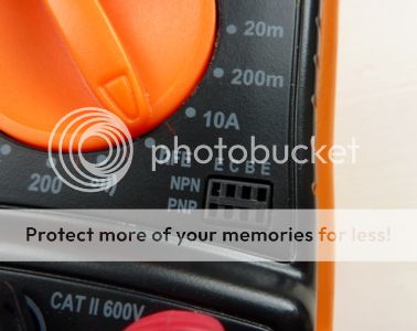
BJTs are easy to match as a lot of Digital Multimeters have the ability to do this. In this case a similar hFE, or forward current gain, is required. This is simply achieved by selecting the relevant setting and plugging the device into the correct connectors.

P1040357_zps71a13d74.jpg


The other devices are a little bit more complicated. The JFETs (part numbers Q1 to Q4) need matching for idss within a tolerance of 10%. As four of these (two each of N-channel and P-channel type) are used per board, that means ordering plenty. The output MOSFETs will need matching for VGS within 0.3volts.

AMB sell matched sets but I wanted to do this myself so ordered untested items from B&D Enterprises.

P1030126.jpg


I put together a quick circuit for testing each type of transistor, JFETs go on the left and MOSFETs on the right, a 12volt DC adaptor provides power and the values can be read with a DMM.

P1030128.jpg


P1030118.jpg


After all of the components have been soldered in place, it's time to wire up and test the sigma power supply. This went without a hitch and I got pretty close to +/- 30 volts.

whf-b22-03_zps26bcb247.jpg


Next come the amp boards. I really thought at the time that it wouldn't be long before there would be sweet sounds emanating from my beta. But during the setup procedure it became apparent that I had made a big gaff and fitted all of the matched JFETs the wrong way round!

It turns out that the silkscreen outline on the PCBs is for another as yet unavailable on the market transistor, the JFETs are mounted another way, obviously I had overlooked this minor detail. At this point I would implore any potential builder of this amplifier to make sure you fully understand what you are doing. Pulling stuff off of boards is no fun at all.

Anyway, after ordering copious amounts of ready matched sets from B&D the boards were ready for action.

P1030569_zps9c5fc297.jpg


Apart from a couple of cold joints the left and right channels worked perfectly. The ground channel was misbehaving and could have been damaged during the initial power up. It was then that I decided to go with a two channel configuration and put the defective board aside for later.
 

lonely boy

New member
Apr 19, 2008
56
0
0
Visit site
Since July 2011 I've tried a few different volume controls, initially an ALPS "Blue Velvet" pot was used for the first couple of weeks, then later installed the rather more expensive Khozmo 48-step attenuator.

P1030169.jpg


I did notice an improvement in sound quality, the ALPS adds some colouration to the sound, the Khozmo is cleaner sounding. But I eventually felt that 48 steps was a little too much and the switch suffered from a slightly annoying click/crack between steps.

Back in went the Blue Velvet but this time the pot was shunted with a resistor, in this case one "naked" Z-Foil per channel, as the pot and the resistor are wired as a variable voltage divider the signal only travels through the latter. I couldn't tell any difference between this configuration and the Khozmo, so I gained sound improvements without the irritating steps getting in the way.

P1030596_zps4943bd14.jpg


After a few months I tried another stepped attenuator, this time a 23-step type. This was provided as a kit from Hifi Collective, OK this isn't cheap but the switching mechanism was much quieter then the previous attenuator and the steps are more then enough for the gain and headphones I use. The switch is made by Seiden and the resistors are Takman carbon films.

P1030588_zpsaebf0802.jpg


P1030590_zpsf099bbb2.jpg


P1030595_zpsce14cb7c.jpg


As the resistors were correctly labelled and bagged, it wasn't difficult to build and didn't take long to put together. I'm happy with it so this attenuator is still currently installed in the amplifier.
 

lonely boy

New member
Apr 19, 2008
56
0
0
Visit site
Going to wrap this project up but lastly I'm going back to discuss the casework.

I wasn't terribly happy with the way the enclosure turned out to be honest. The side cheeks were destined to be eventually replaced at some time, which they recently were, but the top panels looked poor. The 3mm aluminium used is of a lower grade then 5 or 10mm so the finish came out with ugly streaks due to the softer metal, better grades are harder and offer a more consistent finish.

old-case-finish_zps3059885a.jpg


Around a couple of months ago the top and back panels were rubbed down, primed and sprayed with Rustoleum satin black, they look much better. The rather crude expanded aluminium used for the grills was replaced with a finer mesh that was bonded in strips to the underside of the panels.

Early January I ordered some 19mm thick American Walnut from British Hardwoods. New sides were made exactly the same size as before, they were simply finished with few applications of teak oil and lightly waxed and polished. Also at some point bought a pair of DACT stainless steel 38mm knobs.

Before-

old-cases_zps5b3b2339.jpg


old-case-back_zps102256de.jpg


After-

P1040354_zps894995ea.jpg


P1040349_zpsfa573808.jpg


Please excuse the less than steller photography.
 

lonely boy

New member
Apr 19, 2008
56
0
0
Visit site
I am currently populating boards for a balanced/bridged version of this amp.

The plan is to match and install all the transistors over the next week or so and then start testing and troubleshooting.

Hopefully this build will be less :help: and more :dance:
 

TRENDING THREADS

Latest posts