Soldering RCA cables

Isaac Blanc

New member
Sep 21, 2015
2
0
0
Visit site
Hey there,

Before I start, may I just explain that my understanding of audio technology is pretty limited. I’ve taught myself the basics but, as this is for a one-off project rather than the beginnings of a hobby, I don’t know much more.

Right, let’s get into it…

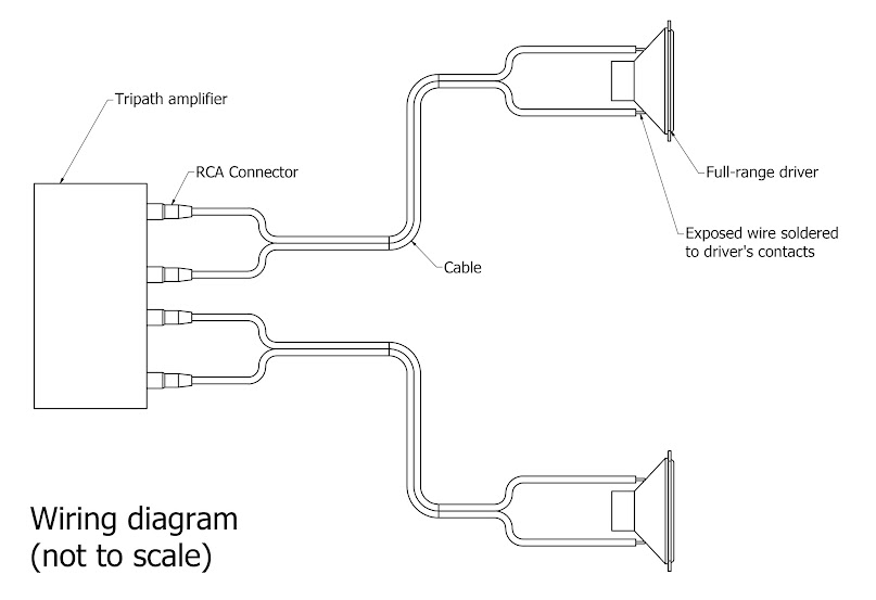
I need to wire a 15W Tripath amp to a pair of 4” 10W full-range drivers. The amp has RCA sockets on the back whilst the drivers just have positive and negative soldering contacts. My plan is to cut a metre-long RCA cable in half and strip the rubber insulation off the exposed ends. This will provide me with two 50cm cables with RCA connectors on one end and exposed wire on the others. I will then solder (and seal with heat-shrink) the two exposed ends of each 50cm cable to the two solder contacts on each driver. The RCA connectors on the other end of each cable will just go straight into the sockets on the back of the amp.

Wiring%2Bdiagram.jpg


Will this work? Up to now, I have just assumed that RCA cables are simply insulated wire with special connectors on each end but, thinking about it, it was stupid to assume this. Are RCA cables instead made up of a group of different wires? Will there be other complications in my plan that I haven’t even thought of?

Any advice would be greatly appreciated.

Thank you all in advance,

Isaac

PS: I'm using Cambridge Audio 100 Series cables.
 

Isaac Blanc

New member
Sep 21, 2015
2
0
0
Visit site
I may not know a lot about audio tech but that was pretty obvious. Thank you for pointing it out!

As I now won't be soldering any RCA cables, my issue is solved. However, I have one other question:

What wires would you suggest I solder the banana plugs to?
 

expat_mike

Well-known member
Mar 30, 2013
160
4
18,595
Visit site
chebby said:
You need 4mm banana plugs for the speaker connections and an RCA phono pair for the single source input.

Before discussing banana plugs, i think Isaac needs to clarify one or two questions.

1 - are the drivers in a loudspeaker cabinet?

2 - does the amp have RCA or babana plug sockets on the back face?
 

chebby

Well-known member
Jun 2, 2008
1,253
26
19,220
Visit site
expat_mike said:
2 - does the amp have RCA or babana plug sockets on the back face?

I posted the picture of the OP's amp above. (A few posts back.)

It has banana sockets for the speaker connections and one set of RCA phonos for the input from the source.

Here, i'll post it again for you ...

AA-AB341_3_b.jpg
 

expat_mike

Well-known member
Mar 30, 2013
160
4
18,595
Visit site
chebby said:
expat_mike said:
2 - does the amp have RCA or babana plug sockets on the back face?

I posted the picture of the OP's amp above. (A few posts back.)

It has banana sockets for the speaker connections and one set of RCA phonos for the input from the source.

Here, i'll post it again for you ...

Sorry I did not realise that was the amp the OP is referring to. I thought that the picture was just to illustrate banana plug sockets.

But it is not clear if the speaker drivers are in a cabinet. If they are, then he needs wires to sockets on the back face of the cabinet, then the cables between the speaker cabinet and the amp back face.
 

Isaac Blanc

New member
Sep 21, 2015
2
0
0
Visit site
The drivers will be in an enclosure but so will the amp. Let me explain a bit about my project...

I am building an iPod dock for a school carpentry project. My design-brief states that is must be a consumer product. Therefore, using it needs to be as simple as plugging a mini-jack into your iPod and hitting 'Play'. This means that it needs to contain an amp so that it can amplify and play music.

I don't have time to go over my designs in detail but I'll post a few diagrams below. If you are interested in the project, you can read this thread where I have discussed many aspects of the design.

[font="Arial, sans-serif"]Here is a computer-rendering of the final product:[/font]

Final%2Bdesign%2B-%2BNo%2Bchamfer.jpg


And here is a cross-section diagram showing how the amp will be contained within the product:

Enclosure%2Bdiagram.jpg


Apologies for any differences between the computer-rendering and the diagram; they were made at different points in the design's development. The diagram is, however, completely up-to-date.

Anyway, now you know a little about my project.

PS: Sorry if this post was a badly written or hard to follow; as usual I'm pretty rushed at the moment.
 

MajorFubar

New member
Mar 3, 2010
690
6
0
Visit site
In which case you're pretty much right. I assume you'll connect the phone/iPod via the headphone socket? That would be fine, all you need is an RCA to 3.5mm jack cable.
 

expat_mike

Well-known member
Mar 30, 2013
160
4
18,595
Visit site
Thanks Isaac,

Your diagrams explain things clearly, and I can now understand what your initial post was referring to.

I have also read through your thread. I think that you will have learnt a lot about engineering a product, by the time you reach the end of your project. One of the key aspects is not to start a project with a firm idea of what the final solution will be - the better way is to evaluate several initial concepts, to see if they will satisfy your needs, then evaluate them for various criteria, such as cost, performance, ease of build, etc. Then choose the best compromise, and turn it into reality.

One of the posters on your thread said that the absolute performance in hifi terms is not the key educational aim of this project. Instead the key aim is for you to understand how to engineer a product, and explain/document it to your teacher. I agree with this, and I get the feeling that you will be fine wwith the documentation/explanation side of things as well.
 

tino

Well-known member
Sep 29, 2011
135
10
18,595
Visit site
Looks very nice .... well done ... but is there any way you can avoid the two exposed screws heads at the front ... one each side. Have you considered using a threaded insert instead?

Another question .... how is the volume controlled?
 

Isaac Blanc

New member
Sep 21, 2015
2
0
0
Visit site
Hey Mike,

Thanks for the reply and for reading my thread. It’s definitely relieving to hear that my designs make some sense!

I like a lot of what you say in your reply. It’s very interesting to learn from someone who (I assume) works in product-design themselves.

expat_mike said:
One of the key aspects is not to start a project with a firm idea of what the final solution will be - the better way is to evaluate several initial concepts, to see if they will satisfy your needs, then evaluate them for various criteria, such as cost, performance, ease of build, etc. Then choose the best compromise, and turn it into reality.

I chose to quote this specific part of your post because it’s something that I really agree with. I think it’s actually quite an exciting part of the creative process not know for sure what your final outcome will be. I would also just like to point out that I did produce eight different initial design ideas from my product specifications which were, in turn, based from extensive market research. I did, as you say, then evaluate those initial concepts before reaching my current design. I’m not trying to say that my design is great, I’m just explaining that a lot of what you say is actually on the corriculum!

I would also agree with your second point: documentation and explanation (folderwork) will make up a huge percentage of my marks. Right now, I think I have about 15 A3 pages going over market research, client’s requirements, existing product analysis, initial design ideas, alternative solutions (it goes on and on).

Isaac :)
 

Isaac Blanc

New member
Sep 21, 2015
2
0
0
Visit site
Hey Tino,

Thank you for the kind words about my project!

In answer to your questions:

tino said:
Looks Have you considered using a threaded insert instead?

Yes. I will probably used old brass ones because I like the slightly industrial look but don't like anything overly shiny. Something like these:

FittingsSleeve.jpg


tino said:
Another question .... how is the volume controlled?

I plan on taking the amp apart whereupon I hope to find that the volume control knob is simply connected to a potentiometer which will, in turn, be connected to three wires. I will de-solder these three wires from the potentiometer, solder them to extension wires and solder those onto the potentiometer. I will then probably drill a hole in the front face of the product, glue the potentiometer to the back of it and the volume knob to the front. I am however aware that I am making lots of assumptions here about the workings of the amp so I may just use one of these.

In short, the volume knob is an aspect of the design that needs a lot more thought. :)
 

tino

Well-known member
Sep 29, 2011
135
10
18,595
Visit site
Isaac Blanc said:
Hey Tino,

Thank you for the kind words about my project!

In answer to your questions:

tino said:
Looks Have you considered using a threaded insert instead?

Yes. I will probably used old brass ones because I like the slightly industrial look but don't like anything overly shiny. Something like these:

tino said:
Another question .... how is the volume controlled?

I plan on taking the amp apart whereupon I hope to find that the volume control knob is simply connected to a potentiometer which will, in turn, be connected to three wires. I will de-solder these three wires from the potentiometer, solder them to extension wires and solder those onto the potentiometer. I will then probably drill a hole in the front face of the product, glue the potentiometer to the back of it and the volume knob to the front. I am however aware that I am making lots of assumptions here about the workings of the amp so I may just use one of these.

In short, the volume knob is an aspect of the design that needs a lot more thought. :)

I envisaged that you would use a threaded insert that screws in behind the front panel, so you don't actually see any screws or inserts on the front face.

Also perhaps a motorised potentiomter kit might work for your volume control if you can find one cheap enough.
 

andyjm

New member
Jul 20, 2012
15
3
0
Visit site
Isaac Blanc said:
Right, now that I have replied to y'all, I have another question of my own:

Bearing in mind that I want optimal sound-quality without breaking the bank, what wire would you recomend I use to connect the amp to the drivers?

Also, fyi, any soldering I do will be with Ersin's 60/40 multicore flux solder.

Given the length of cable, wire choice is not going to make any difference as long as it isn't ludicrously thin. Everyone has a few old 'kettle lead' mains cables kicking around, stripping one of those will give you wire suitable to hook up the drivers. If you want to take a step up just to feel better, then any of the 1.5mm/sq or 2.5mm/sq 'speaker' cables will do. Maplin do some reasonaby priced (less than a couple of £ for the length you will need) cables. Don't use banana plugs at the amp end, they might work loose - better just to strip the cable and use the binding post. It provides a better connection as well (I think the pictures show binding posts).

I wouldn't recommend unsoldering the pot for the volume. It is most likely to be a two-gang pot (one track for each channel) so if you butcher it as you remove it, you may struggle to find a direct replacement. The pot will have 6 connections, and unless you get the screening just right, it will probably introduce some hum. Finally, the circuit board is probably some surface-mount work of art with tracks so small you can't even see half of them. Blundering around with a soldering iron may not be a good idea.

Two choices - use the pot extension shaft you have linked to (I would recommend this), or turn the volume all the way up on the amp and use a generic two gang 10Kohm stereo pot as a voltage divider on the input connections. This may also hum unless you know what you are doing.

Good luck.
 

Isaac Blanc

New member
Sep 21, 2015
2
0
0
Visit site
tino said:
Also perhaps a motorised potentiomter kit might work for your volume control if you can find one cheap enough.

This definitely sounds interesting. Would you mind explaining what a motorised potentiometer is? I'm assuming it's not literally a servo motor that I would attach to my potentiometer.
 

Isaac Blanc

New member
Sep 21, 2015
2
0
0
Visit site
andyjm said:
Given the length of cable...

I've quoted the start of your post so that you know this is in reply to it.

Thanks for explaining about the wires. That sounds perfectly simple. I should be able to get my hands on some suitable wiring pretty easily.

I also understand what you're saying about not using banana connectors. I won't be disconnecting anything once the project is complete so it makes perfect sense to solder straight onto the amp's connectors. One question though: what do you mean by "binding posts"? Personally, I don't see any binding posts on the amp but perhaps that's simply because I misunderstand what they are. Either way, some further explanation here would be great!

Thank you very much for your help regarding potentiometers. I suspected I might encounter such problems but wasn't sure. It's really useful to have someone warn me about this before I go messing things up. Seen as you advise using the extender, I will probably do that. I appreciate you explaining other option though, in case the extender doesn't work out. :)
 

tino

Well-known member
Sep 29, 2011
135
10
18,595
Visit site
Isaac Blanc said:
tino said:
Also perhaps a motorised potentiomter kit might work for your volume control if you can find one cheap enough.

This definitely sounds interesting. Would you mind explaining what a motorised potentiometer is? I'm assuming it's not literally a servo motor that I would attach to my potentiometer.

Something like this ...

RMP_RK16_D_11.GIF


... http://www.alps.com/prod/info/E/HTML/Potentiometer/RotaryPotentiometers/RMP_RK16/RK16812MG099.html

You can get remote control kits for this as well. You can start off with a manually controlled potentiometer and add the remote control afterwards (assuming you allow enouigh space in the cabinet for the electronics and a small hole for the IR sensor)
 

andyjm

New member
Jul 20, 2012
15
3
0
Visit site
Isaac Blanc said:
I also understand what you're saying about not using banana connectors. I won't be disconnecting anything once the project is complete so it makes perfect sense to solder straight onto the amp's connectors. One question though: what do you mean by "binding posts"? Personally, I don't see any binding posts on the amp but perhaps that's simply because I misunderstand what they are.

Looking at the picture of the back of the amp, those speaker connectors are called 'binding posts'. You can either stick a 4mm banana plug down the middle, or if you turn the coloured plastic cover around anticlockwise, it becomes clear that it is actually bonded to a nut on a thread. Undo it a couple of turns and the 'bolt' fixed to the body of the amp usually has a hole drilled across it. Place the bare end of the speaker cable in the hole in the bolt and tighten up the nut and you have a good quality connection. No soldering required. Very common on the back of high end amps and on the back of speaker enclosures.
 

expat_mike

Well-known member
Mar 30, 2013
160
4
18,595
Visit site
Isaac Blanc said:
It’s very interesting to learn from someone who (I assume) works in product-design themselves.

I did spend a decade involved in trying to re-engineer components/assemblies, so that they were cheaper to manufacture - one gradually develops the skill of looking at existing component/assemblies, and visualising how you think they were manufactured/assembled, and wondering if they could have been designed differently geometry/materials/parts reduction etc. This did mean that I felt at home looking at your drawing and 3D model.

If you feel interested, you may enjoy thinking about the two contrasting design approaches, used for consumer music/hifi and computer equipment. On one hand you have the traditional engineering approach, which is to focus on the specifications/performances of the individual components, and then briefly consider the outer case (often not very visually attractive) as the final development activity. The results of this approach can be seen in many generic computers, and probably the amplifier module you will be using. This approach is also recognisable on the forums devoted to DIY audio, where threads contain much discussion about the merits of individual op-Amps or DAC modules, or valves etc, and then everything gets installed into an ugly generic metal case, in order to minimise costs.

In contrast you have the design approach made popular by Apple, which was to devote a lot of time/effort to making sure that the outer case/appearance of the product was asthetically pleasing/tactile etc. Only then would the focus turn onto designing the internal components, so that they would fit inside the case, and still provide the required performance. I think this approach probably applies to much high end (and costly) hifi equipment, because the finished product must be visually appealing, in order to persuade many consumers to open their wallets. In addition, with modern digital based hifi equipment, a lot of the internal componentry consists of standard input boards, standard power supplies, standard DAC boards, and standard amplifier boards, wired together. The clever part is selecting the correct boards, so that they all work well together, however buying such off-the-shelf items, is a lot less effort than spending time/effort designing all the chips/circuitry from first principles.

Back to your project - I still cannot decide if you tended towards the Apple view of design, by deciding on the general look/feel of the enclosure, and then focusing on the internal componentry/connections afterwards.
 

Isaac Blanc

New member
Sep 21, 2015
2
0
0
Visit site
I tried out what you suggested and you were absolutely right. Thank you very much for pointing this out. Embarrissingly, I would probably have never noticed.

I'm assuming that this type of connection is just as strong both physically and electrically as a soldered one. Is this correct?
 

Isaac Blanc

New member
Sep 21, 2015
2
0
0
Visit site
Thank you for your post. I was already aware of these two approaches to design however you summed them up better than I ever could have.

Perhaps stating the obvious here, I think that neither approach is better, they're just suited for different situations. To use some pretty extreme examples, the NASA JPL have produced some of the most wacky-looking designs I've ever seen with minimal attention to aesthetics. This is because they strive for absolute maximum functionality for very proffessional purposes. On the other end of the scale, Apple's products are aimed at an ever less professional target customer who is more interested in superficial aspects of the design such as aesthetics. For this reason, Apple's design are heavily focussed around achieving their very minimalist aesthetic.

There are exceptions though. For example, the interior of SpaceX's so called "Dragon 2" looks ridiculously cool and is also one of the leading technologies in space travel.

NOTE: This last point probably isn't even relevant, I just wanted an excuse to post this image:

download
 

TRENDING THREADS

Latest posts