I'm in the process of buying the parts to produce a passive premap (or more accurately an attenuator) for my dual mono power amps.
I stumbled across the Lightspeed Attenuator while on another forum. The guy who came up with the idea and has been pursuing/developing it for the last 35 years has recently revealed his design to the DIY community. Not altogether sure why he did this...but it is true to say that many mega bucks manufacturers are now using his design approach in their offerings....so the cat is out of the bag as it were.
The original Lightspeed Attenuator can be purchased from here. It doesn't look much does it. However, I've read some fairly convincing testimonies from a large number of buyers / builders and, in principal, the theory appears to back up the claims. So what is the theory.....how does a Lightspeed Attenuator work?
The Theory
A source, let's say a DAC, produces a signal. This signal is provided to the preamplifier. The preamp has a couple of jobs to do. It provides switching between a number of sources and also controls the volume.
The volume is controlled by a potentiometer (pot). This is basically a variable resistor and is comprised a side and a sliding wiper. As you turn the pot the amount of resistance is varied, effecting the current or amount of signal getting through. Therefore, it attenuates the signal as opposed to amplifying it.
Within the preamp the signal may be subsequently amplified (active preamp) or simply passed through (passive) to the power amplifier. The job of the power amplifier is to take the signal provided by the preamp and amplify it to drive the speakers.
The claim is that the volume pot is a flawed device and will always degrade the signal as the contact between the side and the sliding wiper is featherlight and subject to "bounce", i.e. it will wobble about as a result of the signal passing through it, leading to distortion. This has been measured.
So how do you get round this distortion? Well, you could use a stepped attenuator. This switches between a predetermined set of resistors by turning a spindle. The argument against these is that oxidisation can/does form on the contacts and, over time, result in signal degradation.
What else? Well, you can simply select a resistor which will produce the required volume and solder it in place of the volume pot......a very good but not very flexible result.
The Lightspeed attenuator provides a different solution. It uses light dependent resistors (LDRs) to attenuate the signal. The LDR unit contains a light dependent resistor and an LED. As the current to the LEDs is changed, the LED shines brighter or dimmer and, therefore, effects the resistance applied to the signal. The number one benefit, therefore, is the absence of anything other than a resistor in the signal path.
The brightness of the LED is controlled by a pot. The flawed design of the pot doesn't matter as it isn't in the signal path....it merely controls the brightness of the LED.
So how do you make one?
Construction
I can't link to the build site for fear of breaking the house rules, so I'll have to provide a brief summary myself.
Please see the schematic below.
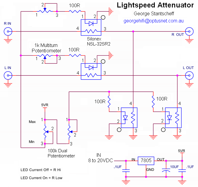
Lightspeed Attenuator schematic
If you follow the path of R IN (on the left) over to R OUT on the right you'll notice that the signal only passes through a resistor (inside the LDR unit). Nothing else is in the signal path. You'll notice in the bottom left the traditional pot which is used to control the current to the right and left LDR units. And that's about it other than the trimpots (multiturn) allow the current provided to each to LED to be precisly matched.
So, this is an easy build. The only other thing required is the provision of a regulated 5VDC supply to power the LEDs via the pot.
The commercially available Lightspeed Attenuator does not permit the switching of sources. Again, it is claimed that oxidation of the switches can degrade the signal and the designer generally frowns on anything unnecessary on the signal path thereby excluding relay switching, etc.
It is claimed that the Lightspeed Attenuator provides a level of transparency unmatched by any other preamp....and has generated a fair bit of excitement within certain DIY communities. A number of high end users are wondering why they have spent a fortune on their preamps and switching to the Lightspeed Attenuator.
So, why am I building one? It is easy to build. The parts are cheap (the LDRs are costing me £20). There is a group buy available of the LDRs on at the moment. And if the claims are true, why would I want anything else?
The LDRs are on order and should be here within a month. Watch this space.
I stumbled across the Lightspeed Attenuator while on another forum. The guy who came up with the idea and has been pursuing/developing it for the last 35 years has recently revealed his design to the DIY community. Not altogether sure why he did this...but it is true to say that many mega bucks manufacturers are now using his design approach in their offerings....so the cat is out of the bag as it were.
The original Lightspeed Attenuator can be purchased from here. It doesn't look much does it. However, I've read some fairly convincing testimonies from a large number of buyers / builders and, in principal, the theory appears to back up the claims. So what is the theory.....how does a Lightspeed Attenuator work?
The Theory
A source, let's say a DAC, produces a signal. This signal is provided to the preamplifier. The preamp has a couple of jobs to do. It provides switching between a number of sources and also controls the volume.
The volume is controlled by a potentiometer (pot). This is basically a variable resistor and is comprised a side and a sliding wiper. As you turn the pot the amount of resistance is varied, effecting the current or amount of signal getting through. Therefore, it attenuates the signal as opposed to amplifying it.
Within the preamp the signal may be subsequently amplified (active preamp) or simply passed through (passive) to the power amplifier. The job of the power amplifier is to take the signal provided by the preamp and amplify it to drive the speakers.
The claim is that the volume pot is a flawed device and will always degrade the signal as the contact between the side and the sliding wiper is featherlight and subject to "bounce", i.e. it will wobble about as a result of the signal passing through it, leading to distortion. This has been measured.
So how do you get round this distortion? Well, you could use a stepped attenuator. This switches between a predetermined set of resistors by turning a spindle. The argument against these is that oxidisation can/does form on the contacts and, over time, result in signal degradation.
What else? Well, you can simply select a resistor which will produce the required volume and solder it in place of the volume pot......a very good but not very flexible result.
The Lightspeed attenuator provides a different solution. It uses light dependent resistors (LDRs) to attenuate the signal. The LDR unit contains a light dependent resistor and an LED. As the current to the LEDs is changed, the LED shines brighter or dimmer and, therefore, effects the resistance applied to the signal. The number one benefit, therefore, is the absence of anything other than a resistor in the signal path.
The brightness of the LED is controlled by a pot. The flawed design of the pot doesn't matter as it isn't in the signal path....it merely controls the brightness of the LED.
So how do you make one?
Construction
I can't link to the build site for fear of breaking the house rules, so I'll have to provide a brief summary myself.
Please see the schematic below.
Lightspeed Attenuator schematic
If you follow the path of R IN (on the left) over to R OUT on the right you'll notice that the signal only passes through a resistor (inside the LDR unit). Nothing else is in the signal path. You'll notice in the bottom left the traditional pot which is used to control the current to the right and left LDR units. And that's about it other than the trimpots (multiturn) allow the current provided to each to LED to be precisly matched.
So, this is an easy build. The only other thing required is the provision of a regulated 5VDC supply to power the LEDs via the pot.
The commercially available Lightspeed Attenuator does not permit the switching of sources. Again, it is claimed that oxidation of the switches can degrade the signal and the designer generally frowns on anything unnecessary on the signal path thereby excluding relay switching, etc.
It is claimed that the Lightspeed Attenuator provides a level of transparency unmatched by any other preamp....and has generated a fair bit of excitement within certain DIY communities. A number of high end users are wondering why they have spent a fortune on their preamps and switching to the Lightspeed Attenuator.
So, why am I building one? It is easy to build. The parts are cheap (the LDRs are costing me £20). There is a group buy available of the LDRs on at the moment. And if the claims are true, why would I want anything else?
The LDRs are on order and should be here within a month. Watch this space.
 Twitter